TR-124 – Functional Requirements for Broadband Residential Gateway Devices
Issue: 9
Issue Date: July 2024
List of Figures
- WPS pushbutton method state machine
- WAN PPPoE automated connection flow
- WAN IPv6 automated connection flow
- Receive router advertisement subroutine flow
- Upstream Queuing and Scheduling Example for RG
- Example: No WAN Connection Configuration
- Example: Router Sets Up PPPoE to an ISP
- Example: PC3 sets up its own PPPoE Session
- Example: Router sets up a Second PPPoE Session
- Example: Router in 2684 Bridged Mode with DHCP Server On
- Example: Router in Bridged Mode with DHCP Server On
- Example: Router in Bridged Mode with DHCP Server off
- Example: Single PC Mode of Operation
- Example: Example: Router in Routed 2684 Mode
- Example: Router sets up Second IP Connection
- Example: Managed Bridge Configuration
- Example: Unmanaged Bridge Configuration
- Sealing current reference design
List of Tables
Notice
The Broadband Forum is a non-profit corporation organized to create guidelines for broadband network system development and deployment. This Technical Report has been approved by members of the Forum. This Technical Report is subject to change. This Technical Report is owned and copyrighted by the Broadband Forum, and all rights are reserved. Portions of this Technical Report may be owned and/or copyrighted by Broadband Forum members.
Intellectual Property
Recipients of this Technical Report are requested to submit, with their comments, notification of any relevant patent claims or other intellectual property rights of which they may be aware that might be infringed by any implementation of this Technical Report, or use of any software code normatively referenced in this Technical Report, and to provide supporting documentation.
Terms of Use
1. License
Broadband Forum hereby grants you the right, without charge, on a perpetual, non-exclusive and worldwide basis, to utilize the Technical Report for the purpose of developing, making, having made, using, marketing, importing, offering to sell or license, and selling or licensing, and to otherwise distribute, products complying with the Technical Report, in all cases subject to the conditions set forth in this notice and any relevant patent and other intellectual property rights of third parties (which may include members of Broadband Forum). This license grant does not include the right to sublicense, modify or create derivative works based upon the Technical Report except to the extent this Technical Report includes text implementable in computer code, in which case your right under this License to create and modify derivative works is limited to modifying and creating derivative works of such code. For the avoidance of doubt, except as qualified by the preceding sentence, products implementing this Technical Report are not deemed to be derivative works of the Technical Report.
2. NO WARRANTIES
THIS TECHNICAL REPORT IS BEING OFFERED WITHOUT ANY WARRANTY WHATSOEVER, AND IN PARTICULAR, ANY WARRANTY OF NONINFRINGEMENT AND ANY IMPLIED WARRANTIES ARE EXPRESSLY DISCLAIMED. ANY USE OF THIS TECHNICAL REPORT SHALL BE MADE ENTIRELY AT THE USER’S OR IMPLEMENTER’S OWN RISK, AND NEITHER THE BROADBAND FORUM, NOR ANY OF ITS MEMBERS OR SUBMITTERS, SHALL HAVE ANY LIABILITY WHATSOEVER TO ANY USER, IMPLEMENTER, OR THIRD PARTY FOR ANY DAMAGES OF ANY NATURE WHATSOEVER, DIRECTLY OR INDIRECTLY, ARISING FROM THE USE OF THIS TECHNICAL REPORT, INCLUDING BUT NOT LIMITED TO, ANY CONSEQUENTIAL, SPECIAL, PUNITIVE, INCIDENTAL, AND INDIRECT DAMAGES.
3. THIRD PARTY RIGHTS
Without limiting the generality of Section 2 above, BROADBAND FORUM ASSUMES NO RESPONSIBILITY TO COMPILE, CONFIRM, UPDATE OR MAKE PUBLIC ANY THIRD PARTY ASSERTIONS OF PATENT OR OTHER INTELLECTUAL PROPERTY RIGHTS THAT MIGHT NOW OR IN THE FUTURE BE INFRINGED BY AN IMPLEMENTATION OF THE TECHNICAL REPORT IN ITS CURRENT, OR IN ANY FUTURE FORM. IF ANY SUCH RIGHTS ARE DESCRIBED ON THE TECHNICAL REPORT, BROADBAND FORUM TAKES NO POSITION AS TO THE VALIDITY OR INVALIDITY OF SUCH ASSERTIONS, OR THAT ALL SUCH ASSERTIONS THAT HAVE OR MAY BE MADE ARE SO LISTED.
All copies of this Technical Report (or any portion hereof) must include the notices, legends, and other provisions set forth on this page.
Issue History
| Issue Number | Approval Date | Issue Editor | Changes |
|---|---|---|---|
| Issue 1 | December 2006 |
|
|
| Issue 2 | May 2012 |
|
|
| Issue 3 | August 2012 |
|
|
| Issue 4 | October 2014 |
|
|
| Issue 5 | August 2016 |
|
|
| Issue 6 | November 2020 |
|
|
| Issue 7 | December 2021 |
|
|
| Issue 8 | December 2022 |
|
|
| Issue 9 | July 2024 |
|
|
Comments or questions about this Broadband Forum Technical Report should be directed to info@broadband-forum.org.
Broadband User Services Work Area Directors
- Jason Walls, QA Cafe
- John Blackford, Vantiva
Executive Summary
TR-124 specifies a superset of requirements for broadband Residential Gateway (RG) devices that are capable of supporting a full suite of voice, data, broadcast video, video on demand and two-way video applications in broadband networks.
The requirements are grouped into modules. This means that an RG can be specified by listing the modules that the RG is expected to support. No single device is expected to support all modules.
Requirements are sometimes modified when a new TR-124 revision is created. It is therefore necessary for any identification of modules supported (or to be supported) by a RG also note which TR-124 revision was used to generate the module list.
TR-124 Issue 2 updated TR-124 Issue 1 to include requirements for IPv6.
TR-124 Issue 3 clarifies and corrects TR-124 Issue 2 and defines new profiles.
TR-124 Issue 4 defines several new profiles.
TR-124 Issue 5:
takes into account the deprecation of TR-064 Issue 1 in favor of Issue 2 (adding the MGMT.LOCAL.TR-064 profile and fixing text in several places),
takes into account the deprecation by UPnP Forum of UPnP IGD V1.0 in favor of UPnP IGD V2.0,
defines the new WAN.TRANS.MAP-E profile for MAP-E support.
TR-124 Issue 6:
- Adds security requirements for RGs
- Adds requirements for G.fast enabled RGs
- Adds requirements for TWAMP performance measurement
- Adds requirements for 5G-RG in Wireless-Wireline Convergence (WWC) architecture
TR-124 Issue 7:
- Updates the 5G-WWC requirements and adds two new IF requirements for fixed RGs with LTE or NR interfaces.
- Adds SEC.FIRMWARE for firmware authentication and encryption requirements.
1 Purpose and Scope
1.1 Purpose
TR-124 presents a superset of requirements for broadband Residential Gateway devices that are capable of supporting a full suite of voice, data, broadcast video, video on demand and two-way video applications in broadband networks.
1.2 Scope
A Residential Gateway implementing the general requirements of TR-124 will incorporate at least one embedded WAN interface, routing, bridging, a basic or enhanced firewall, one or multiple LAN interfaces and home networking functionality that can be deployed as a consumer self-installable device.
TR-124 specifies a baseline of Residential Gateway device and application functions needed to support service delivery in routed and bridged broadband network architectures. Devices can be specified that will operate on any of the different types of Broadband Forum defined network architectures. This allows service providers to configure a Residential Gateway supporting specified TR-124 modular requirements locally via TR-064i2 and Web Graphical User Interface or remotely via TR-069.
TR-124 provides optional requirements modules for various physical broadband interfaces (e.g. xDSL, Ethernet, GPON) and home networking (LAN) interfaces that may be implemented on Residential Gateways to meet local service provider needs. Furthermore, to accommodate common region-specific service provider requirements that do not apply globally, additional regional annexes are included in the TR-124 requirements that may be included in region-specific product profiles (e.g. North American Power and Environmental requirements).
It is intended that these general requirements modules and WAN/LAN interface modules can be used as references to define a specific product implementation that may be needed in future Broadband Forum Technical Reports. This checklist style product profile approach (shown in the “Product Profile Template” section in APPENDIX VI is intended to provide an easy mechanism to define a specific product that is needed by region or by service providers. An example of such a product profile is TR-068 Base Requirements for an ADSL Modem with Routing, which refers to TR-124 feature modules and regional annexes.
These requirements are both backward and forward-looking. They attempt to address the needs of current DSL services and architectures as well as starting to address future needs. Some requirements have been included in support of TR-059, TR-064i2, TR-069, TR-101i2 and TR-122. Any CPE that claims to be compliant with these technical requirements must meet the requirements that reference those documents. It is understood that a CPE that does not claim to be compliant with these referenced requirements may or may not meet any or all of these requirements. On a periodic basis, new general requirements and physical interface modules may be added in future revisions of TR-124.
Requirements are sometimes modified when a new TR-124 revision is created. It is therefore necessary for any identification of modules supported (or to be supported) by a RG also note which TR-124 revision was used to generate the module list.
2 References and Terminology
2.1 Conventions
In this Technical Report, several words are used to signify the requirements of the specification. These words are always capitalized.
| MUST | This word, or the term “REQUIRED”, means that the definition is an absolute requirement of the specification. |
|---|---|
| MUST NOT | This phrase means that the definition is an absolute prohibition of the specification. |
| SHOULD | This word, or the term “RECOMMENDED”, means that there could exist valid reasons in particular circumstances to ignore this item, but the full implications need to be understood and carefully weighed before choosing a different course. |
| SHOULD NOT | This phrase, or the phrase “NOT RECOMMENDED” means that there could exist valid reasons in particular circumstances when the particular behavior is acceptable or even useful, but the full implications need to be understood and the case carefully weighed before implementing any behavior described with this label. |
| MAY | This word, or the term “OPTIONAL”, means that this item is one of an allowed set of alternatives. An implementation that does not include this option MUST be prepared to inter-operate with another implementation that does include the option. |
| By Default | These words indicate that this is a default setting or operation of the unit that MUST be configurable if provided. This term is not included in RFC 2119 [56]. |
Other residential gateway type features not identified in this document may also be implemented in the device. An implementation that includes features not identified in this document must be prepared to inter-operate with implementations that do not include these features.
References to CPE or LAN devices indicate other equipment such as hosts including PCs and workstations.
In certain cases, TR-124 generically refers to new LAN or WAN interface performance monitoring data parameters that have not been specifically defined in the requirements at the time of the publishing of this document. As these requirements are not yet defined, it is expected that vendors may support parameter extensions and basic interface traffic performance statistics until such a time that the Broadband Forum defines further Technical Reports to support new interface parameter data models for possible use with TR-064i2, TR-069 and the Web GUI.
2.2 References
The following references constitute provisions of this Technical Report. At the time of publication, the editions indicated were valid. All references are subject to revision; users of this Technical Report are therefore encouraged to investigate the possibility of applying the most recent edition of the references listed below.
A list of currently valid Broadband Forum Technical Reports is published at www.broadband-forum.org.
NOTE – A number of IETF drafts are cited in this document. Due to the fact that home networking standards and technology are still being rapidly developed, this was considered necessary. If subsequent drafts or RFCs are published, they will obsolete the draft cited in this document.
The following information is given for the convenience of users of this Technical Report and does not constitute an endorsement by the Broadband Forum of these products:
Safari® is a registered trademark of Apple Computer, Inc.
HomePlug® is a registered trademark of HomePlug Powerline Alliance, Inc.
HomePNA® is a registered trademark of HomePNA, Inc.
IEEE® is a registered trademark of the Institute of Electrical and Electronics Engineers, Inc. (IEEE). This publication is not endorsed by the IEEE.
Internet Explorer® and Microsoft® are registered trademarks of Microsoft Corporation.
Java® and JavaScript® are registered trademarks of Oracle, Inc.
Mozilla® is a registered trademark of the Mozilla Foundation.
Wi-Fi® is a registered trademark of the Wi-Fi Alliance
WPA, WPA2,WPA3, Protected Setup, WMM and WMM-SA are trademarks of the Wi-Fi Alliance
2.3 Definitions
| Term | Definition |
|---|---|
| 5G-RG | An RG acting as UE with regard to the 5G core. It holds a secure element and exchanges NAS signaling with the 5G core. |
| 5G Access Network (5GAN) | This comprises 5G radio ANs (RANs) and 5G wireline ANs connecting to a 5G core. |
| 5G System (5GS) | A system consisting of 5G Access Network (AN), 5G Core Network and end-device. |
| Access & Mobility Function (AMF) | The AMF is a 5GC-CP function that terminates N1, the control interface with UEs, and N2, the control interface with access networks. It is responsible for mobility & access related functions. It acts as the security anchor point for a given UE. At PDU session establishment, it selects the SMF corresponding to the requested slice and targeted DN, and relays session related messages to this SMF. |
| ACS | Auto-Configuration Server. This is a component in the broadband network responsible for CWMP auto-configuration of the CPE for advanced services. |
| Agent | A generic term that refers (as appropriate) to either a CWMP Endpoint or to a USP Agent. |
| Allowed NSSAI | NSSAI provided by the serving PLMN network during e.g. a registration procedure, indicating the S-NSSAIs value that the UE could use in the serving PLMN of the current registration area. (definition from TS 23.501 [x]) |
| Backup | The ability to take over a task when a source becomes unavailable.
Examples: - A web server becomes unavailable. For incoming traffic, backup provides another web server to take over the operation. - A communication link becomes unavailable. Via backup, another link takes over the communication task. |
| Configurable | A requirement for configurability does not imply any particular configuration interface. When specific user or TR-069 or other configurability is required, the requirement is stated explicitly. |
| Configured NSSAI | An NSSAI that has been provisioned in the 5G-RG applicable to one or more PLMN (definition from TS 23.501 [20]). |
| Connection | As used in this document, a connection is the continuing ability to communicate over a pair of IP addresses. |
| Controller | A generic term that refers (as appropriate) to either a CWMP ACS or a USP Controller. |
| CPE | Customer Premises Equipment; refers (as appropriate) to any CWMP-enabled or USP-enabled device and therefore covers both Internet Gateway devices and LAN-side end devices. |
| CWMP | CPE WAN Management Protocol. Defined in TR-069 [3], CWMP is a communication protocol between an ACS and CWMP-enabled CPE that defines a mechanism for secure auto-configuration of a CPE and other CPE management functions in a common framework. |
| CWMP Endpoint | A CWMP termination point used by a CWMP-enabled CPE for communication with the ACS. |
| Device | Unless otherwise qualified, the term device refers to an RG. |
| Enabling | Likewise, controllability requirements, for example to enable or disable a feature, do not imply a control interface. |
| Failover | The ability to automatically switch to another source when a source
becomes unavailable. Examples: - A web server becomes unavailable. For incoming traffic, failover automatically provides another web server to take over the operation. - A communication link becomes unavailable. Via failover, another link automatically takes over the communication task. |
| GUI | The term GUI or web GUI implies access to the RG that is visible to the end user. The use of this term in a requirement is an assertion that control or information display is available to the end user. |
| Load balancing | The ability to divide the working load of a task over multiple
sources in an equal way. Examples: - A web service that is run by a web server. For incoming traffic this can be equally divided over multiple servers by a load balancer. - A communication link that is supporting a communication task. Various links can be used to equally divide the communication load by a load balancer. This can be for incoming and outgoing traffic. Thus, load balancing is only one form of load sharing: load balancing is load sharing where the load is equally divided over the sources. What defines “equal” depends on the use case and metrics used. |
| Load sharing | The ability to divide the working load of a task over multiple
sources. Examples: - A web service that is run by a web server. For incoming traffic this can be divided over multiple servers by load sharing. - A communication link that is supporting a communication task. Various links can be used to divide the communication load by load sharing. This can be for incoming and outgoing traffic. |
| Logs | Likewise, requirements for logging do not imply log configurability and retrieval on any particular interface unless stated explicitly. |
| Network Instance | Information identifying a domain. Used by the UPF for traffic detection and routing (definition from TS 23.501 [20]). |
| Network Slice | A logical network that provides specific network capabilities and network characteristics (definition from TS 23.501 [20]). |
| Network Slice Instance | A set of Network Function instances and the required resources (e.g. compute, storage and networking resources) which form a deployed Network Slice (definition from TS 23.501 [x]). |
| NSI ID | An identifier for a Network Slice instance (definition from TS 23.501 [20]). |
| Network Slice Selection Assistance Information (NSSAI) | The NSSAI is a collection of S-NSSAIs. An NSSAI may be a Configured NSSAI, a Requested NSSAI or an Allowed NSSAI. There can be at most eight S-NSSAIs in Allowed and Requested NSSAIs sent in signaling messages between the UE and the Network. |
| NSSP (Network Slice Selection Policy) | It is the set of SM-NSSAI that a UE is authorized to access. It is stored in the UE and corresponds to the NSSAI in the subscriber information in the network database. |
| Operator-specific configuration | Many requirements specify defaults, but then add the phrase, “or use an operator-specific configuration.” This phrase recognizes that operators may override TR-124 requirements when necessary to satisfy their specific needs. |
| PDU session | Temporal association between the UE and a Data Network that provides a PDU connectivity service. A session can be IP, Eth or unstructured. |
| Requested NSSAI | NSSAI provided by the UE to the Serving PLMN during registration (definition from TS 23.501 [20]). |
| RG | A residential gateway (RG) is a device that interfaces between the WAN and LAN IP environment for a consumer broadband customer. It may route or bridge traffic, depending on its configuration and specifications. The term RG is retained for historical continuity, even though some features may be directed at business applications. |
| Smart RG | A smart residential gateway is a residential gateway with additional smart home services. |
| Software application | A Software application consists of one or more software modules and configuration data, and provides specific function(s) using the open platform API of a Smart RG. |
| Software module | An installable software entity which includes executables, libraries, configuration and other data. |
| Subscribed S-NSSAI | S-NSSAI based on subscriber information, which a UE is subscribed to use in a PLMN (definition from TS 23.501 [20]). |
| USP | Universal Service Platform. Defined in TR-369 [6], USP is an evolution of CWMP that allows applications to manipulate Service Elements in a network of Controllers and Agents. |
| USP Agent | A USP Agent is a USP Endpoint that exposes Service Elements to one or more USP Controllers |
| USP Controller | A USP Controller is a USP Endpoint that manipulates Service Elements through one or more USP Agents. |
| Wireline 5G Access Network (W-5GAN) | This is a wireline AN that can connect to a 5G core via the AGF. The egress interfaces of a W-5GAN form the border between access and core. They are N2 for the control plane and N3 for the user plane. |
2.4 Abbreviations
This Technical Report defines the following abbreviations:
| 5WE | 5G WWC Encapsulation |
|---|---|
| AAA | Authentication, Authorization and Accounting |
| AAL | ATM Adaptation Layer |
| ac | alternating current |
| ADSL | Asynchronous Digital Subscriber Line |
| AFTR | Address family transition router |
| AGF | Access Gateway Function |
| ALG | Application Layer Gateway |
| AMF | Access Management Function |
| AN | Access Network |
| ANSI | American National Standards Institute |
| AS | Access Stratum |
| ASCII | American Standard Code for Information Interchange |
| ATA | Analog Terminal Adapter |
| ATM | Asynchronous Transfer Mode |
| BFD | Bidirectional forwarding detection |
| CP | Control Plane |
| CPE | Customer Premises Equipment |
| CRC | Cyclic Redundancy Check |
| CSA | Canadian Standards Association |
| DAD | Duplicate address detection |
| DHCP | Dynamic Host Configuration Protocol |
| DLNA | Digital living network alliance (www.dlna.org) |
| DNS | Domain Name Server |
| DoS | Denial of Service |
| DSCP | Differentiated Services Code Point |
| DSL | Digital Subscriber Line |
| DUID | DHCP Unique Identifier |
| DUID-EN | DUID based Enterprise Number |
| FCC | Federal Communications Commission |
| FQDN | Fully Qualified Domain Name |
| GMT | Greenwich Mean Time |
| GUI | Graphical User Interface |
| HTML | Hypertext Markup Language |
| HTTP | Hypertext Transfer Protocol |
| HTTPS | Secure Hypertext Transfer Protocol |
| Hz | Hertz |
| IAID | Identification Association Identifier |
| IEEE® | The Institute of Electrical and Electronics Engineers |
| IETF | The Internet Engineering Task Force |
| IMEI | International Mobile Equipment Identity |
| IMSI | International Mobile Subscriber Identity |
| INP | Impulse noise protection |
| IP | Internet Protocol |
| IPCP | Internet Protocol Control Protocol |
| ISO | International Organization for Standardization |
| ITU | International Telecommunication Union |
| Kbps | kilobits per second |
| LAN | Local Area Network |
| LCP | Link Control Protocol |
| LPF | Low-pass filter |
| MAC | Medium Access Control |
| MRU | Maximum Receive Unit |
| ms | millisecond |
| MTBF | Mean Time Between Failure |
| MTU | Maximum Transit Unit |
| NAS | Non-Access Stratum |
| NAT | Network Address Translation |
| NTP | Network Time Protocol |
| ONU | Optical Network Unit |
| PADI | PPPoE Active Discovery Initiation |
| PADO | PPPoE Active Discovery Offer |
| PC | Personal Computer |
| PCP | Priority Code Point |
| PD | Prefix Delegation |
| PDU | Protocol Data Unit |
| POTS | Plain Old Telephone Service |
| PPP | Point to Point Protocol |
| PVC | Permanent Virtual Circuit |
| QFI | QoS Flow Identifier |
| RA | Router Advertisement |
| RG | Residential Gateway |
| RQI | Reflective QoS Indication |
| RTSP | Real time streaming protocol |
| SIP | Session Initiation Protocol |
| SN | Serial Number |
| SNTP | Simple Network Time Protocol |
| SSL | Secure Sockets Layer |
| SUCI | Subscriber Concealed Identifier |
| SUPI | Subscriber Permanent Identifier |
| TCP | Transmission Control Protocol |
| TLS | Transport Layer Security |
| TR | Technical Report |
| UDP | User Datagram Protocol |
| UE | User Equipment |
| UL | Underwriters Laboratories |
| ULA | User licensing agreement |
| ULC | Underwriters Laboratories Canada |
| UP | User Plane |
| URSP | UE Route Selection Policy |
| USB | Universal Serial Bus |
| Vac | Volts ac |
| VCI | Virtual Circuit Identifier |
| Vdc | Volts dc |
| VDSL | Very high-speed Digital Subscriber Line |
| VID | VLAN Identifier |
| VLAN | Virtual LAN |
| VoIP | Voice over IP |
| VPI | Virtual Path Identifier |
| VSO | Vendor Specific Option |
| WAN | Wide Area Network |
| WEP | Wireless Encryption Protocol |
| Wi-Fi® | Wi-Fi Alliance wireless standards organization |
| WPA | Wi-Fi Protected Access |
| WWC | Wireline Wireless Convergence |
3 Technical Report Impact
3.1 Energy Efficiency
TR-124 contains regional power requirements for Residential Gateway (RG) devices. In general, there is an expectation that these devices will meet all local regulatory requirements for powering and energy consumption.
3.2 IPv6
Issue 2 of this Technical Report was published specifically to provide requirements needed for deployment of IPv6 capable RGs. Issue 3 includes a number of minor extensions, corrections and clarifications.
3.3 Security
The requirements in TR-124 are intended to provide a reasonably secure environment for general consumers, while ensuring that the functionality is usable by consumers, such that they do not feel that the degree of security is preventing them from accomplishing what they want to do.
The requirements are also intended to ensure that the RG does not have a negative impact on the security of the access network and other users of the access network.
3.4 Privacy
TR-124 does not explicitly address privacy requirements.
4 Residential Gateway Requirements
4.1 GEN – General Device Requirements
4.1.1 GEN.DESIGN – Design
| ID | Requirement |
|---|---|
| GEN.DESIGN.1 | The RG MUST be compact and have a physical profile suitable for a desktop. |
| GEN.DESIGN.2 | The RG SHOULD be able to be wall mounted and stand on its side. |
| GEN.DESIGN.3 | The RG MAY have the ability to be mounted horizontally or vertically. |
| GEN.DESIGN.4 | If wall mounted, the RG SHOULD be oriented so that the cabling is routed toward the ground in order to reduce strain on the cabling. |
| GEN.DESIGN.5 | A detachable wall-mounting bracket MAY be added to the RG. |
| GEN.DESIGN.6 | The power connector at the RG MUST be securely connected to avoid accidental disconnect. This means that the connector MUST be either secured via a clip to the box or be held in place with significant force so that it does not readily pull out by minor pulling on the power cord. |
| GEN.DESIGN.7 | If the power supply is external to the RG, it SHOULD be labeled with the RG vendor’s name and the model number of the RG. |
| GEN.DESIGN.8 | If the power supply is external to the RG it SHOULD be either small enough, or appropriately positioned on the power cord, so as not to block other power outlets. |
| GEN.DESIGN.9 | If the power cable includes an AC to DC conversion brick, that brick MAY have a light on it. |
| GEN.DESIGN.10 | The RG MUST NOT be USB powered. |
| GEN.DESIGN.11 | The RG MUST NOT use the local phone loop for power. |
| GEN.DESIGN.12 | The model and serial number of the RG MUST be visible via external markings on the RG. |
| GEN.DESIGN.13 | The model and serial number of the RG MUST be visible via external markings on the RG packaging. |
| GEN.DESIGN.14 | If a console port used for local technician configuration is provided on the RG, it SHOULD NOT be physically accessible to end users (e.g. it should not be placed on the outside of the device). |
| GEN.DESIGN.15 | The RG MUST have a single function reset button in order to reset the device to the default factory settings. |
4.1.2 GEN.OPS – Device Operation
| ID | Requirement |
|---|---|
| GEN.OPS.1 | All RG firmware and associated system files MUST be pre-installed. |
| GEN.OPS.2 | The RG MUST operate 24 hours a day, 7 days a week without the need to reboot. |
| GEN.OPS.3 | The MTBF (Mean Time Between Failures) of the RG and operating system SHOULD be equal to or exceed 1 year (e.g. it should not need a reboot more than one time per year). |
| GEN.OPS.4 | The life expectancy of the RG SHOULD be at least seven years. |
| GEN.OPS.5 | The RG SHOULD tolerate power fluctuations and brown-outs, continuing to operate normally and maintaining its configuration after these events. |
| GEN.OPS.6 | The RG SHOULD be able to detect faults and reset appropriately upon detection. |
| GEN.OPS.7 | The RG SHOULD include sufficient non-volatile memory to accommodate future control and data plane protocol upgrades over a minimum of four years. The potential upgrades may include: initiating and terminating signaling protocols at IP and ATM layers; logic for packet classification, policing, forwarding, traffic shaping and QoS support at IP, Ethernet and ATM layers. |
| GEN.OPS.8 | The RG MUST preserve local configuration information during power-off and power interruption. |
| GEN.OPS.9 | The RG MUST complete power up in 60 seconds or less. |
| GEN.OPS.10 | The RG SHOULD be self-installable by an end user in under 20 minutes assuming the default configuration and mode of operation. This is the time from when the box is opened to when the user is using the service including any driver installation (assuming no network complications and excluding micro-filter installation and customer ordering/registration). |
| GEN.OPS.11 | Other than networking drivers (e.g. USB, wireless, etc…), other software or drivers MUST NOT be required on computers and other devices for proper and full use of the RG. |
| GEN.OPS.12 | The RG, its drivers and any packaged software SHOULD support Macintosh OS 8.6 and above. |
| GEN.OPS.13 | The RG, its drivers and any packaged software SHOULD support all Microsoft PC based operating systems that have not yet reached “End of Support” status (see http://support.microsoft.com/lifecycle for more details). |
| GEN.OPS.14 | The RG, its drivers and any packaged software MAY support Linux. It is especially desirable to do so with an open interface. |
| GEN.OPS.15 | The RG MUST preserve its configuration across firmware updates. |
| GEN.OPS.16 | All software revisions SHOULD be backward compatible with all previous versions. There SHOULD be no loss of existing functionality. |
| GEN.OPS.17 | Software revisions MUST NOT require service provider network changes to maintain proper operation of previous features. |
| GEN.OPS.18 | The RG firmware MUST be identified by a revision number. This revision number MUST be formatted using an X.Y.Z incremental numbering format where X indicates the major release number, Y indicates the minor release number, and Z represents the revision number (e.g. 2.4.1). |
| GEN.OPS.19 | The RG vendor SHOULD have a web site where firmware updates and documentation are available. |
| GEN.OPS.20 | The firmware at the RG vendor’s web site SHOULD include all error correcting updates for the RG. |
GEN.OPS.21 |
The RG MUST NOT allow “back door” entry to the unit (e.g. there must be no hidden telnet or web access using secret passwords). This requirement is not intended to preclude physically secured craft access in accordance with GEN.DESIGN.14. |
| GEN.OPS.22 | All firmware updates MUST be verified using security mechanisms. A checksum mechanism is a minimum requirement for achieving this. |
| GEN.OPS.23 | All firmware updates SHOULD be signed with a cryptographic “fingerprint” of at least 256 bits. |
GEN.OPS.24 |
In the event of a failure occurring during an update, the RG MUST be able to back off to the prior version of the firmware installed on the RG. That is, the prior version of the RG’s firmware MUST continue to be useable in the event that a firmware update fails to complete. This is not a requirement for a dual image, although that is one manner in which this requirement might be satisfied. |
4.1.3 GEN.NET – Networking Protocols
| ID | Requirement |
|---|---|
| GEN.NET.1 | The RG MUST support Ethernet (IEEE 802.3). |
| GEN.NET.2 | The RG MUST support IP Version 4. |
| GEN.NET.3 | If the RG does not support IPV6, it SHOULD be software configurable or upgradeable to support IP Version 6 in the future. This means that the processing power, memory and networking components be designed appropriately and be sufficiently robust to provide this support. |
GEN.NET.4 |
The RG MUST support the TCP, IP, UDP, routing and associated IETF protocols identified here:
IANA Directory of General Assigned Numbers (http://www.iana.org/numbers.html) |
| GEN.NET.5 | The RG MUST support IP over Ethernet. |
| GEN.NET.6 | The RG MUST support, at a minimum, a 256 MAC address table for LAN devices. |
4.1.4 GEN.NETv6 – IPv6 Networking Protocols
| ID | Requirement |
|---|---|
| GEN.NETv6.1 | The RG MUST support IP Version 6, which is defined in RFC 2460 [63]. |
| GEN.NETv6.2 | The RG MUST support enabling and disabling of IPv6. |
4.2 WAN – Wide Area Networking
4.2.1 WAN.ATM – WAN.ATM
| ID | Requirement |
|---|---|
| WAN.ATM.1 | The RG MUST support standard ATM (AAL5) payload format. Note: this satisfies Broadband Forum TR-101 R-371. |
| WAN.ATM.2 | The RG MUST perform AAL Segmentation and Reassembly (SAR), Convergence Sublayer (CS) functions and CRC check. |
| WAN.ATM.3 | The RG MUST support encapsulation of bridged Ethernet over AAL5 (without FCS) as described in RFC 2684 [71]. |
| WAN.ATM.4 | The RG MUST be able to use both LLC-SNAP and VC-MUX (null) encapsulation over AAL5 with all supported protocols. The default MUST be LLC-SNAP. |
| WAN.ATM.5 | The RG MAY support encapsulation of IP over AAL5, per RFC 2684 [71]. |
| WAN.ATM.6 | If the RG supports IP over AAL5, it MAY support classical IP according to RFC 2225 [60]. |
| WAN.ATM.7 | The RG MUST support ATM CoS. UBR, CBR and VBR-rt MUST be supported, as defined in AF-TM-0121.000 [28]. |
| WAN.ATM.8 | VBR-nrt and UBR with per VC queuing SHOULD be supported. |
| WAN.ATM.9 | The default ATM CoS for the primary VC MUST be UBR. |
| WAN.ATM.10 | The RG SHOULD support auto configuration as defined in Broadband Forum TR-062 [1] and ILMI 4.0 and its extensions. |
| WAN.ATM.11 | The RG MUST always respond to ATM testing, pings and loopbacks according to ITU-T I.610 [174] (F4, F5). |
| WAN.ATM.12 | The RG SHOULD support initiating an ATM loopback and receiving the reply. This satisfies Broadband Forum TR-101 R-370. |
| WAN.ATM.13 | The RG MUST provide a default CPID of all 1s (FFFF). This satisfies Broadband Forum TR-101 [30] R-372. |
| WAN.ATM.14 | The RG MUST support 0/35 as the default VPI/VCI for the first PVC or use an operator-specific configuration. |
WAN.ATM.15 |
The RG MUST be able to perform an auto search for the VPI/VCI settings for the first PVC based on a definable search list VPI/VCI sequence order. If the RG reaches a state of session establishment (e.g. IP when the RG is responsible for session termination) after performing the auto search, the default VPI/VCI settings MUST be set to the newly discovered values. The new default pair MUST be stored on the RG across power off situations. If an ATM connection cannot be established after power is restored, the search process starts over again. |
WAN.ATM.16 |
The RG MUST support the following default VPI/VCI auto-search list programmed as a factory default setting in the following sequence, or use an operator-specific sequence configuration: 0/35, 0/38, 8/35, 0/43, 0/51, 0/59, 8/43, 8/51. This default list MUST be overwriteable via the methods discussed in WAN.ATM.18. |
| WAN.ATM.17 | The RG MUST be configurable so that the auto-search mechanism can be disabled. |
| WAN.ATM.18 | The RG MUST allow the auto-search list to be redefined using TR-064i2 and interfaces. |
| WAN.ATM.19 | The default VPI/VCI values for all PVCs MUST be configurable. The default value MUST be utilized prior to performing an auto-search but should exclude the default value in the auto-search. |
| WAN.ATM.20 | The RG MUST support VPI values from 0 to 255 |
| WAN.ATM.21 | The RG MUST support VCI values from 32 to 65535 |
4.2.1.1 WAN.ATM.MULTI – ATM Multi-PVC
| ID | Requirement |
|---|---|
| WAN.ATM.MULTI.1 | The RG MUST support eight PVCs. This is in addition to support for any implemented ATM UNI control path PVCs (e.g. ILMI auto-configuration PVC, etc.). |
| WAN.ATM.MULTI.2 | The RG MUST allow the protocol stack (e.g. IP over Ethernet, PPPoE, PPPoA, etc.) for each provisioned PVC to be defined separately. If necessary, each PVC can use a different stack and set of protocols. |
| WAN.ATM.MULTI.3 | There is no default defined VPI/VCI for additional PVCs past the primary PVC defined in WAN.ATM above. The RG MUST support auto-search function (see WAN.ATM.16 through 19) on all PVCs and will use the same auto-search sequence identified (skipping over any already in use). |
| WAN.ATM.MULTI.4 | The RG MUST NOT require the same VPI value for all supported PVCs. |
| WAN.ATM.MULTI.5 | All supported PVCs MUST be able to be active and sending/receiving traffic simultaneously. See requirements LAN.FWD.9, 10, 11 and 15 for more details on interface selection for routing. |
WAN.ATM.MULTI.6 |
The RG MUST support the minimum ATM granularity applicable to the associated DSL protocol in use on a per VC and VP basis. For example, ATM granularity of 32 kbps MUST be supported for ADSL on a per VC and VP basis. |
| WAN.ATM.MULTI.7 | The RG MUST use the same Ethernet MAC address for all interfaces over the same AAL5/ATM/DSL connection. |
| WAN.ATM.MULTI.8 | The RG MUST support multiple levels of CoS simultaneously across separate VCCs (e.g. UBR for PVC 0/35 and CBR for PVC 0/43 where both PVCs are active simultaneously). |
4.2.2 WAN.CONNECT – Connection Establishment
Note that this module applies to IPv6 connections as well as IPv4, but only if the RG has an IPv6 stack.
| ID | Requirement |
|---|---|
| WAN.CONNECT.1 | The RG MUST support an “always on” mode for connections. In this mode the RG MUST NOT time out connection sessions (ATM, IP and PPP) and MUST automatically re-establish any sessions after disconnection, lease expiration or loss and restoration of power. |
| WAN.CONNECT.2 | Moved to WAN.CONNECT.ON-DEMAND.1 and 4 |
WAN.CONNECT.3 |
The RG MUST support a “manual connect” option for connections. In this mode the connection to the broadband network is initiated manually through the Web GUI or via TR-064i2 request and, by default, terminates only when done so explicitly by the user, due to a power loss or when the connection is lost. |
| WAN.CONNECT.4 | Moved to WAN.CONNECT.ON-DEMAND.6 |
| WAN.CONNECT.5 | A manual way of disconnecting without waiting for a connection timeout MUST be provided. |
| WAN.CONNECT.6 | Moved to WAN.CONNECT.ON-DEMAND.7 |
| WAN.CONNECT.7 | The RG MUST follow all standards required to perform an orderly tear down of the associated connections involved at the associated network levels (e.g. issue a DHCP Release message when using DHCPv4, issue LCP Terminate-Request/Terminate-Ack and PADT packet when using PPPoE, etc.) and then restart the connections. |
| WAN.CONNECT.8 | The RG MUST detect the loss of communications with a network identified DNS server as indicated by a failed query, and log the event. |
4.2.2.1 WAN.CONNECT.ON-DEMAND – On-Demand Connection Establishment
The On-demand Connection function applies only to IPv4 connections. However, when IPv6 is present, its behavior must take the presence of IPv6 into consideration as described in this module
| ID | Requirement |
|---|---|
| WAN.CONNECT.ON-DEMAND.1 | The RG MUST support a “connect on demand” option for IPv4 connections that run over PPP. In this mode, the connection to the broadband network is initiated when outbound traffic is encountered from the local LAN and terminated after a timeout period in which no traffic occurs. |
| WAN.CONNECT.ON-DEMAND.2 | If the PPP session only contains IPv4, then the RG MUST terminate the PPP session in accordance with WAN.CONNECT.ON-DEMAND.1, and any associated PPPoE session (if applicable). |
| WAN.CONNECT.ON-DEMAND.3 | If the PPP session contains IPv4 and IPv6, then the RG MUST terminate only the IPv4 session. This is done using IPCP commands. |
| WAN.CONNECT.ON-DEMAND.4 | The RG MUST support a “connect on demand” option for IPv4 connections that run over Ethernet. |
| WAN.CONNECT.ON-DEMAND.5 | To determine whether a connection has IPv4 activity during a timeout interval, the RG MUST consider only traffic with an IPv4 ethertype. |
| WAN.CONNECT.ON-DEMAND.6 | The interval after which a connection timeout occurs MUST be able to be configured. |
| WAN.CONNECT.ON-DEMAND.7 | A default timeout of 20 minutes SHOULD be used for connection timeouts or use an operator-specific configuration. |
| WAN.CONNECT.ON-DEMAND.8 | If the RG has an active IPv6 connection, and does not have addresses for DNS recursive name servers to be accessed over IPv6, then the “connect on demand” option MUST be disabled. |
4.2.3 WAN.ETHOAM – Ethernet OAM
| ID | Requirement |
|---|---|
| WAN.ETHOAM.1 | The RG MUST support a maintenance end point (MEP) at the customer and access link levels on a per VLAN basis. Note: The multi-PVC case is for further study. This satisfies Broadband Forum TR-101 [30] R-285, R-294. |
| WAN.ETHOAM.2 | The RG MUST support a default ME level value of 5 for the customer level. This satisfies TR-101 [30] R-286. |
| WAN.ETHOAM.3 | The RG SHOULD support a loopback message (LBM) function at the customer level that can generate a multicast LBM toward its peer MEP(s). This satisfies TR-101 [30] R-287. |
| WAN.ETHOAM.4 | The RG MUST support a loopback reply (LBR) function at the customer level toward its peer MEP(s) in response to both unicast and multicast LBMs. This satisfies TR-101 [30] R-288. |
| WAN.ETHOAM.5 | The RG MUST support a linktrace reply (LTR) function at the customer level toward its peer MEP(s). This satisfies TR-101 [30] R-289. |
| WAN.ETHOAM.6 | For business customers and/or premium customers requiring proactive monitoring, the RG SHOULD support generating continuity check messages (CCMs) at the customer level. This satisfies TR-101 [30] R-290. |
| WAN.ETHOAM.7 | The RG MUST support turning off sending of CCMs at the customer level, while keeping the associated MEP active. This satisfies TR-101 [30] R-291. |
| WAN.ETHOAM.8 | The RG MUST support receiving AIS messages at the customer level. This satisfies TR-101 [30] R-292. |
| WAN.ETHOAM.9 | The RG SHOULD trigger the appropriate alarms for loss of continuity at the customer level. This satisfies TR-101 [30] R-293. |
| WAN.ETHOAM.10 | The RG MUST support a default ME level value of 1 for the access link level. This satisfies TR-101 [30] R-295. |
| WAN.ETHOAM.11 | The RG SHOULD support a loopback message (LBM) function at the access link level that can generate a multicast LBM toward its peer MEP(s). This requirement allows the RG to dynamically learn the MAC address of the AN MEP, and test the connectivity to that MEP. This satisfies TR-101 [30] R-296. |
| WAN.ETHOAM.12 | The RG MUST support a loopback reply (LBR) function at the access link level toward its peer MEP(s), in response to both unicast and multicast LBMs. This satisfies TR-101 [30] R-297. |
| WAN.ETHOAM.13 | The RG MUST issue a DHCP renewal message following a random delay between 1 and 30 seconds after it detects a restoration of Ethernet continuity at the customer ME level. |
4.2.4 WAN.BRIDGE – Bridging
Note that the IPv6 parts of this module apply only if the RG supports IPv6.
| ID | Requirement |
|---|---|
| WAN.BRIDGE.1 | The RG MUST be able to bridge IPv4 over Ethernet. |
| WAN.BRIDGE.2 | The RG MUST be a learning bridge as defined in IEEE 802.1D for all logical and physical Ethernet interfaces, supporting a minimum of 272 MAC addresses. |
WAN.BRIDGE.3 |
If bridge mode is enabled for IPv4 on the RG by default for LAN connected devices, the RG MUST be able to support additional connections to a Controller for remote management addressability (using direct DHCPv4 or static IPv4, PPP, etc.), and connections for any locally terminated service that require IP (v4 or v6) addressability (e.g. gateway integrated voice ATA ports, etc.). Note that this special bridge mode that includes a device remote management session connection requires an additional WAN connection from the network. This requirement is considered conditional as a result of the network side dependency, but the RG must support this type of configuration. |
| WAN.BRIDGE.4 | The RG MUST be able to bridge IPv6 over Ethernet (Ethertype 0x86DD). This includes bridging of multicast frames. |
| WAN.BRIDGE.5 | The RG MUST be able to configure IPv6 bridging for a WAN interface, separate from IPv4 treatment. |
| WAN.BRIDGE.6 | The RG MUST be able to configure IPv6 bridging separately for each WAN interface (if there are multiple WAN interfaces). |
| WAN.BRIDGE.7 | When IPv6 bridging is enabled on a WAN interface, the RG MUST be configurable to act as a host on that WAN interface (doing SLAAC, etc.). It will not request IA_PD, since that is not a host function. |
4.2.5 WAN.DHCPC – DHCP Client (DHCPv4)
| ID | Requirement | |||||||||||||||
|---|---|---|---|---|---|---|---|---|---|---|---|---|---|---|---|---|
WAN.DHCPC.1 |
The RG MUST be able to obtain IPv4 network information dynamically on its WAN interface. This information includes IPv4 address, primary and secondary DNS addresses and default gateway address. Dynamically obtaining IPv4 network information is accomplished using DHCP (v4) and / or IPCP (IPv4). |
|||||||||||||||
| WAN.DHCPC.2 | If the RG is not configured to use a static IPv4 address and the RG fails to detect a PPPoE or DHCPv4 server, then the RG MUST set its WAN IPv4 address to an undefined value, in order to prevent it from retaining its prior IPv4 address. | |||||||||||||||
| WAN.DHCPC.3 | If a RG is functioning as a DHCPv4 client, it MUST identify itself in option 61 (client-identifier) in every DHCPv4 message in accordance with RFC 4361 [103]. | |||||||||||||||
WAN.DHCPC.4 |
For the DUID portion of option 61 in DHCPv4 as described in RFC 4361 [103] , the RG MUST follow the DUID-EN format specified in ID 9.3 of RFC 3315 [81]. The RG MUST use Broadband Forum enterprise-number value 3561 in the DUID-EN enterprise-number field. For the identifier field of the DUID-EN, the RG MUST use an ASCII string containing the same content and formatted according to the same rules as defined for the HTTP username in ID 3.4.4 of TR-069 [3], if CWMP is used for remote management. |
|||||||||||||||
WAN.DHCPC.5 |
The RG IAID value in DHCPv4 and DHCPv6 MUST be a 32 bit number encoded in network byte order. In cases where the RG is functioning with a single DHCP client identity, it MUST use value 1 for IAID for all DHCP interactions. IAID is defined in RFC 3315 [81]. In cases where the RG is functioning with multiple DHCP client identities, the values of IAID have to start at 1 for the first identity and be incremented for each subsequent identity. The RG’s mapping of IAID to its physical aspects or logical configuration SHOULD be as non-volatile as possible. For example, the RG MAY use IAID value 1 for the first physical interface and value 2 for the second. Alternatively, the RG MAY use IAID value 1 for the virtual circuit corresponding to the first connection object in the data model and value 2 for the second connection object in the data model. |
|||||||||||||||
| WAN.DHCPC.6 | The DUID-EN field value MAY be printed on the RG label. | |||||||||||||||
WAN.DHCPC.7 |
A RG functioning as a DHCPv4 client MUST identify its manufacturer OUI, product class, model name and serial number using vendor-specific options as defined in RFC 3925 [91]. Specifically, it MUST use option 125. Note that with exception of ModelName, the data contained in this option will be redundant with what is included in the Device ID in option 61. However, this is desirable because these two options serve different purposes. The data in option 125 allows the DHCPv4 server to be pre-configured with policy for handling classes of devices in a certain way without requiring the DHCPv4 server to be able to parse the unique format used in client-identifier option (which can also vary in TR-181 depending on presence of a ProductClass value). On the other hand, the client-identifier serves as an opaque but predictable identifier. It is predictable because it is the same identifier as used by the RG for interactions with other services. The same identifier is used for HTTP authentication and in SSL client certificates. Each sub-option value to be provided in option 125 MUST be treated as a string encoded into binary using UTF-8. The data MUST be encapsulated in option 125 under enterprise code 3561 decimal (0x0DE9), corresponding to the IANA “ADSL Forum” entry in the Private Enterprise Numbers registry. A specific sub-option is defined for each value. The value must match the corresponding TR-181 [35] parameter as defined in the following table:
If the value of a parameter is empty, the sub-option MUST be omitted. |
|||||||||||||||
| WAN.DHCPC.8 | The RG MUST be able to request DHCPv4 option 42 for NTP server information as per RFC 2132 [58]. | |||||||||||||||
| WAN.DHCPC.9 | To obtain the local time zone, the RG SHOULD be able to request one of the following DHCPv4 options: Option 100 (PCode) or Option 101 (TCode) in accordance with RFC 4833 [110]. |
4.2.5.1 WAN.DHCPC.Force – Force renew
| ID | Requirement |
|---|---|
| WAN.DHCPC.Force.1 | The RG MUST support the use of DHCP force renew ([77]) for changing the configuration parameters or the IP address associated with an IP session. |
| WAN.DHCPC.Force.2 | The RG MUST support sending the FORCERENEW_NONCE_CAPABLE option in the DHCP discover and in the DHCP request messages, as per RFC 6704 [132]. |
| WAN.DHCPC.Force.3 | The RG MUST support using the Forcerenew nonce for validating DHCP ForceRenew messages received from the DHCP server, as per RFC 6704 [132]. |
4.2.5.2 WAN.DHCPC.BFDecho – BFD echo
| ID | Requirement |
|---|---|
| WAN.DHCPC.BFDecho.1 | The RG SHOULD support configuration of the BFD echo functionality, as per RFC 5881 [119], for both IPv4 and IPv6. |
| WAN.DHCPC.BFDecho.2 | The RG SHOULD support sending BFD echo packet(s) on its WAN interface at regular intervals using a recommended default of 30s. The destination IP address of such packets MUST be taken from the list of IP addresses assigned to or via the WAN interface, including the Subnet-Router address of an IPv6 DHCPv6 delegated prefix. |
| WAN.DHCPC.BFDecho.3 | The RG SHOULD support receiving self-originated BFD echo packets addressed to its assigned address or the Subnet-Router IPv6 delegated prefix. |
| WAN.DHCPC.BFDecho.4 | Unless overridden by configuration, by default after a failure of 3 successive BFD echo intervals, the RG MUST issue a DHCP renew message following a random jitter interval between 1 and 30 seconds. |
4.2.5.3 WAN.DHCPC.BFDKA – BFD Keep-alive
| ID | Requirement |
|---|---|
| WAN.DHCPC.BFDKA.1 | RG MUST support the BFD protocol for IP Session Keep-alive. The BFD implementation MUST be compliant with the BFD standard as described in the RFC 5880 [118] . |
| WAN.DHCPC.BFDKA.2 | BFD MUST be initiated after both the RG and the IP Edge’s IP addresses are available on the RG. |
| WAN.DHCPC.BFDKA.3 | The RG MUST take on the Passive role during BFD session initiation. |
| WAN.DHCPC.BFDKA.4 | The RG MUST support BFD Demand mode |
| WAN.DHCPC.BFDKA.5 | The RG MUST support BFD Asynchronous mode. |
| WAN.DHCPC.BFDKA.6 | The RG MUST be able to process BFD echo packets in the data plane as specified in RFC 5881 [119]. |
| WAN.DHCPC.BFDKA.7 | The RG MUST be able to configure the DSCP bits of BFD packets. |
| WAN.DHCPC.BFDKA.8 | The RG MUST be able to configure the Ethernet Priority bits of BFD packets. |
| WAN.DHCPC.BFDKA.9 | The RG SHOULD respond to IP Edge initiated BFD polls using the same DSCP and Ethernet Priority values received in the packet |
| WAN.DHCPC.BFDKA.10 | The RG MUST ignore IP packets arriving on the BFD UDP port other than those originating on the IP Edge. |
| WAN.DHCPC.BFDKA.11 | The BFD configuration on the RG MUST be configurable using Broadband Forum TR-069 [3]. |
| WAN.DHCPC.BFDKA.12 | When using BFD Demand mode, the RG MUST run an inactivity timer based on the Detect Interval negotiated with the IP Edge. |
WAN.DHCPC.BFDKA.13 |
When a BFD session on the RG receives a poll with a Diag code set to “Path Down” it MUST perform the following actions:
|
| WAN.DHCPC.BFDKA.14 | The RG DHCP client MUST be able to enter DHCPv4 Init-Reboot state or DHCPv6 Confirm state upon detecting that BFD has transitioned into “Down” state. |
| WAN.DHCPC.BFDKA.15 | The RG MUST use the IP Edge address as the destination for BFD Control packets. |
WAN.DHCPC.BFDKA.16 |
The RG MUST be able to be pre-provisioned with the following Broadband Forum specified default configuration:
|
4.2.6 WAN.DHCPv4 – DHCP Client (DHCPv4)
4.2.6.1 WAN.DHCPv4.ERP – EAP Re-authentication (ERP) for DHCPv4
| ID | Requirement |
|---|---|
| WAN.DHCPv4.ERP.1 | The RG MUST support the DHCP Relay Agent Information Option RFC 3046 [75]. |
| WAN.DHCPv4.ERP.2 | The RG MUST support receiving a DHCPv4 request message from a UE client, which includes a Parameter Request List Option requesting the DHCPv4 ERP Local Domain Name, i.e. the domain name of the ERP server of the local domain to which that client is attached. The DHCPv4 request message may be Discovery or Request. |
| WAN.DHCPv4.ERP.3 | If the RG has the ERP Local Domain Name from authentication server for a client during a previous AAA exchange, it SHOULD include it in the DHCPv4 LDN sub-option in a Relay Agent Information Option RFC 3046 [75] and forward to the DHCPv4 server. |
| WAN.DHCPv4.ERP.4 | The RG MUST support relaying a DHCPv4 Reply Message with the DHCPv4 ERP Local Domain Name option from the DHCPv4 server to the client. |
| WAN.DHCPv4.ERP.5 | The RG MUST support configuration of the parameters for it to connect to the RADIUS or Diameter server via Web GUI or Controller extension. |
4.2.7 WAN.DHCPv6 – DHCP Client (DHCPv6)
4.2.7.1 WAN.DHCPv6.ERP – EAP Re-authentication (ERP) for DHCPv6
| ID | Requirement |
|---|---|
| WAN.DHCPv6.ERP.1 | The RG MUST support the ERP Local Domain Name (LDN) DHCPv6 Option ([130]). |
| WAN.DHCPv6.ERP.2 | The RG MUST support receiving a DHCPv6 request message from a UE client, which includes an Option Request option requesting the DHCPv6 ERP Local Domain Name option ([130]). The DHCPv6 request message may be Solicit, Request, or Information Request. |
| WAN.DHCPv6.ERP.3 | If the RG has pre-existing knowledge of the ERP local domain name for a client (for example, from a previous AAA exchange), it SHOULD include it in an instance of the DHCPv6 ERP Local Domain Name option of the DHCPv6 message and forward it to the DHCPv6 server as a sub-option of the Relay-Supplied Options option ([128]). |
| WAN.DHCPv6.ERP.4 | The RG MUST support relaying a DHCPv6 Reply Message with the DHCPv6 ERP Local Domain Name option from the DHCPv6 server to the client. |
| WAN.DHCPv6.ERP.5 | The RG MUST support configuration of the parameters for it to connect to the RADIUS or Diameter server via Web GUI or Controller extension. |
4.2.8 WAN.IPv6 – IPv6 WAN Connection
| ID | Requirement |
|---|---|
| WAN.IPv6.1 | The RG MUST support automated establishment of an IPv6 connection according to the flow in Annex A.2. |
| WAN.IPv6.2 | The RG MUST support a dual stack of IPv4 and IPv6 running simultaneously, as described in section 2 of RFC 4213 [99]. |
| WAN.IPv6.3 | The RG MUST allow the IPv6 stack to be enabled / disabled. |
| WAN.IPv6.4 | The RG MUST support DHCPv6 client messages and behavior per IETF RFC 3315. See WAN.DHCPC.5 for further specifics on IAID value. |
| WAN.IPv6.5 | The RG MUST support the role of the CPE requesting router in RFC 3633 [87]. |
| WAN.IPv6.6 | The RG MUST support specifying in its DHCPv6 prefix delegation request an indication of the length of prefix it requires. If the RG supports multiple LANs, or has PD requests from its LAN, it MUST indicate a preferred prefix length that would at least enable the RG to assign a /64 prefix to each LAN it supports. Note that the delegated prefix may vary from the requested length. |
| WAN.IPv6.7 | When sending DHCPv6 messages, the RG MUST identify itself in OPTION_CLIENTID (1) (client-identifier) using the same client identifier as for IPv4 (see WAN.DHCPC.3 and .4). |
| WAN.IPv6.8 | The RG MUST support IPv6 node requirements as a host node, per RFC 6434 [129]. |
| WAN.IPv6.9 | The RG MUST support stateless address auto-configuration (SLAAC) as a host, per RFC 4862 [112]. |
| WAN.IPv6.10 | The RG MUST support receipt of route information per RFC 4191 [97]. If the RG only has one WAN connection, it does not need to place this information in its routing table, but it does need to save it (for possible forwarding on the LAN interface). |
| WAN.IPv6.11 | If route information is provided (RFC 4191 [97]) and the RG has multiple WAN connections, it MUST place the route information in its routing table. |
WAN.IPv6.12 |
If the RG does not have a globally-scoped address on its WAN interface after having been delegated a prefix, it MUST create addresses for itself from the delegated prefix. It MUST have at least one address and MAY have more. There is currently no algorithm defined for address creation. It should be assumed that different service providers will want different rules for how to create the address, how many addresses to create, and in the case of multiple addresses, how the different addresses are used. |
| WAN.IPv6.13 | Requirement deleted; redundant with WAN.IPv6.3 |
| WAN.IPv6.14 | The RG MUST be able to request the following DHCPv6 options: IA_NA (RFC 3315), reconfigure accept (RFC 3315 [81]), IA_PD (RFC 3633 [87]), and DNS_SERVERS ([88]). |
| WAN.IPv6.15 | The RG SHOULD be able to request the following DHCPv6 options: SNTP_SERVERS ([96]), domain search list ([88]), and Client FQDN ([109]). |
| WAN.IPv6.16 | The RG MUST be configurable as to which DHCPv6 options it requests via DHCPv6. |
| WAN.IPv6.17 | The connectivity parameters (obtained via RA and DHCPv6) MUST persist across loss of WAN connection (or lack of response from WAN connection). |
| WAN.IPv6.18 | The RG MUST continue to use the connectivity parameters (obtained via RA or DHCP) and consider them valid until either they expire or the RG is explicitly told to use different values. |
| WAN.IPv6.19 | The RG MUST NOT advertise any address prefixes on the WAN using the IPv6 neighbor discovery protocol, or advertise itself as a default router. |
| WAN.IPv6.20 | The RG MUST provide up to 4 instances of option-data within a single OPTION_VENDOR_OPTS (17) (RFC 3315 [81]) with IANA “ADSL Forum” Enterprise Number as the enterprise-number. Each instance will have one of the 4 sub-options from WAN.DHCPC.7 as the vendor-specific opt-code, with the corresponding value in the vendor-specific option-data. If the value of a parameter is empty for the RG, then the sub-option MUST be omitted. If there are no values to provide, the entire option MUST be omitted. |
| WAN.IPv6.21 | The RG SHOULD be able to request the following DHCPv6 options: address selection policy ([136]) and DNS selection policy ([133]). |
| WAN.IPv6.22 | If route information is provided (draft-ietf-mif-dhcpv6-route-option) and the RG has multiple WAN connections, it MUST place the route information in its routing table. |
| WAN.IPv6.23 | The RG SHOULD generate address selection policy based on policies obtained from each WAN link by DHCPv6 option (draft-ietf-6man-addr-select-opt) or manually configured policy. |
| WAN.IPv6.24 | The RG MUST be able to request DHCPv6 option OPTION_NTP_SERVER(56) for NTP server information as per RFC 5908 [121]. |
| WAN.IPv6.25 | To obtain the local time zone, the RG SHOULD be able to request one of the following DHCPv6 options: OPTION_NEW_POSIX_TIMEZONE(41) or OPTION_NEW_TZDB_TIMEZONE(42) in accordance with RFC 4833 [110]. |
4.2.9 WAN.TRANS – Transitional IPv6 WAN Connection
4.2.9.1 WAN.TRANS.6rd – 6rd Transition Mechanism
| ID | Requirement |
|---|---|
| WAN.TRANS.6rd.1 | The RG MUST support the 6rd transition mechanism as described in RFC 5969 [122]. This includes being able to configure the necessary parameters from the Controller and via DHCPv4, creation of the prefix, using the created prefix as a “delegated prefix” for purpose of including one of its /64s in RA messages, and modifying the IP header for traffic that goes between the WAN and LAN devices. |
| WAN.TRANS.6rd.2 | The RG MUST support enabling and disabling of the 6rd feature on the “default” routed IPv4 connection. 6rd is not applicable to bridged WAN interfaces. |
| WAN.TRANS.6rd.3 | If the RG supports configuration mechanisms other than the 6rd DHCPv4 option 212 (user-entered, Controller configured, etc.), the RG MUST support 6rd in “hub and spoke” mode. 6rd in “hub and spoke” mode requires all IPv6 traffic to go to the 6rd border relay. In effect, this requirement removes the “direct connect to 6rd” route defined in section 7.1.1 of RFC 5969 [122]. |
4.2.9.2 WAN.TRANS.DS-Lite – Dual Stack Lite Transition Mechanism
| ID | Requirement |
|---|---|
| WAN.TRANS.DS-Lite.1 | The RG MUST support DS-Lite (RFC 6333 [126]) with IPv4 in IPv6 encapsulation (RFC 2473 [64]). |
| WAN.TRANS.DS-Lite.2 | This requirement replaced by requirement WAN.TRANS.DS-Lite.6. |
| WAN.TRANS.DS-Lite.3 | The RG MUST configure a static IPv4 default route toward the DS-Lite tunnel. |
| WAN.TRANS.DS-Lite.4 | The RG MUST deactivate the NAPT function on the DS-Lite interface. |
| WAN.TRANS.DS-Lite.5 | The RG MUST support enabling and disabling of DS-Lite. |
| WAN.TRANS.DS-Lite.6 | The RG MUST be able to use the DHCPv6 option to retrieve the FQDN of the AFTR element, as defined in RFC 6334 [127]. |
| WAN.TRANS.DS-Lite.7 | Manual configuration on the RG of the FQDN or the IPv6 address of the AFTR element SHOULD be supported. |
| WAN.TRANS.DS-Lite.8 | Remote configuration from a Controller of the FQDN or the IPv6 address of the AFTR element SHOULD be supported. |
| WAN.TRANS.DS-Lite.9 | The RG MUST support configurable precedence between the FQDN and the IPv6 address. |
| WAN.TRANS.DS-Lite.10 | The RG MUST support configurable precedence between dynamic or static configuration of the IPv6 address of the AFTR element when both are available. The RG MUST use DHCPv6 by default or use an operator-specific configuration. |
4.2.9.3 WAN.TRANS.v4-release-control – IPv6 connectivity with content-based IPv4 release control transition
mechanism {#req:wan.trans.v4-release-control}
| ID | Requirement |
|---|---|
| WAN.TRANS.v4-release-control.1 | The RG MUST provide a mechanism that monitors IPv4 session/traffic. |
| WAN.TRANS.v4-release-control.2 | The RG MUST provide a timer-based trigger for releasing an IPv4 address. |
| WAN.TRANS.v4-release-control.3 | The RG MUST provide signaling to the BNG according to RFC 1332 [50]. |
| WAN.TRANS.v4-release-control.4 | The RG MUST provide the (re)assignment of an IPv4 address inside a PPP session according to RFC 1332 [50], independent of the IPv6CP status according to section 2.1 of RFC 4241 [100]. |
| WAN.TRANS.v4-release-control.5 | The timer that triggers the release of the IPv4 address MUST be configurable. |
| WAN.TRANS.v4-release-control.6 | The timer that triggers the release of the IPv4 address MUST be configurable from a Controller. |
4.2.9.4 WAN.TRANS.MAP-E – IPv6 connectivity with content-based IPv4 release control transition
mechanism {#req:wan.trans.map-e}
| ID | Requirement |
|---|---|
| WAN.TRANS.MAP-E.1 | The RG MUST support mapping of address and port with encapsulation method (MAP-E) as specified in RFC 7597 [138]. |
| WAN.TRANS.MAP-E.2 | The RG MUST support the configuration for MAP-E operation by one or more methods, including Controller provided, DHCPv6 with options as specified in RFC 7598 [139]. |
| WAN.TRANS.MAP-E.3 | The RG MUST support the MAP-E configuration for parameters with consistence as specified in RFC 7598 [139]. |
| WAN.TRANS.MAP-E.4 | The RG MUST support enabling and disabling of MAP-E operation. |
| WAN.TRANS.MAP-E.5 | When performing NAT44 function, the RG MUST restrict the port assignment within the range per MAP-E configuration. |
| WAN.TRANS.MAP-E.6 | The RG MUST support MAP-E operation in “hub and spoke” mode by forwarding IPv4-in-IPv6 packets to the MAP-E BR for distribution. |
| WAN.TRANS.MAP-E.7 | The RG SHOULD be able to connect to more than one MAP-E domain. |
4.2.10 WAN.PPP – PPP Client
| ID | Requirement |
|---|---|
| WAN.PPP.1 | The RG MUST support PPP and the associated protocols as defined in IETF RFCs 1332, 1334, 1661, 1877, 1994. |
| WAN.PPP.2 | Upon receipt of non-standard or unrecognized PPP extensions according to IETF RFCs 1570 and 2153 from the broadband network (e.g. vendor or proprietary), the RG MUST operate without fault. |
| WAN.PPP.3 | The RG MUST support PPPoE as defined in RFC 2516 [67]. |
| WAN.PPP.4 | The RG MUST support RFC 4638 [107] in order to accommodate MTU/MRU values greater than 1492 bytes in PPPoE. |
| WAN.PPP.5 | If the RG supports ATM, the RG SHOULD support PPP over AAL5 (PPPoA) as defined in RFC 2364 [61]. |
| WAN.PPP.6 | The RG MUST be able to save all logins and passwords for PPP sessions originated by the RG. Passwords MUST NOT be available outside the RG (that is, they cannot be queried or displayed). |
| WAN.PPP.7 | The RG MUST NOT immediately terminate PPPoE sessions and upper layer protocol connections when the physical connection is lost. It should defer the teardown process for two minutes. If the physical connection is restored during that time, the RG MUST first attempt to use its previous PPPoE session settings. If these are rejected, then the original PPPoE session is to be terminated and a new PPPoE session attempted. |
| WAN.PPP.8 | The RG SHOULD incorporate a random timing delay prior to starting each IP (v4 or v6) and PPP session. This random timing delay helps to reduce connection failures when a group of users attempts to establish connections to a service provider at the same time (e.g. after power is restored to a neighborhood that had a blackout). |
| WAN.PPP.9 | If the RG receives an authentication failure when attempting an automated PPP connection attempt, it SHOULD re-try immediately to establish the connection. After three unsuccessful attempts, the RG SHOULD wait for five minutes, then repeat the connection attempt three times. If authentication still fails, the RG SHOULD back off to thirty minute intervals between groups of three attempts. |
| WAN.PPP.10 | If the RG is using the PPPoE client function actively, the RG MUST be able to forward PPPoE sessions initiated from LAN devices as additional PPPoE sessions to the WAN interface (this is sometimes known as PPPoE pass-through). Specifically, these LAN initiated PPPoE sessions MUST NOT be tunneled inside the RG’s primary PPPoE client session. |
| WAN.PPP.11 | When fragmentation is required, the RG MUST fragment all PPP sessions that it originates on an access VC using MLPPP interleaving as defined in RFC 1990 [54]. |
WAN.PPP.12 |
If PPP is used, the RG MAY obtain an IPv4 subnet mask on its WAN interface using IPCP (IPv4) extensions. If this is done, the IPv4 subnet masks will be communicated with IPCP (IPv4) using the PPP IPCP (IPv4) option with option code 144, the length of the option being 6 and the mask being expressed as a 32-bit mask (e.g. 0xFFFFFF80), not as a number indicating the consecutive number of 1s in the mask (from 0 to 32). The learned network information MAY, but need not, be used to populate the LAN side embedded DHCP server for the RG. The learned network information is treated as a subnet and not as a collection of individual addresses. That is, the first and last addresses in the subnet should not be used. The IPv4 address negotiated SHOULD, but need not, be the one assigned to the RG. |
| WAN.PPP.13 | The RG MUST make the access concentrator name used with PPPoE connections available via the Web GUI, TR-064i2, and for a Controller for diagnostic purposes. |
| WAN.PPP.14 | The RG MUST support RFC 3544 [83], “IP Header Compression over PPP”. |
4.2.10.1 WAN.PPP.IPv6 – PPP Client for establishment of IPv6 connection
| ID | Requirement |
|---|---|
| WAN.PPP.IPv6.1 | The RG MUST support IPv6 over PPP per RFC 5072 [113] and RFC 5172 [114]. |
| WAN.PPP.IPv6.2 | The RG MUST support establishment of an IPv6 over PPPoE connection according to the flow in Annex A.1. |
| WAN.PPP.IPv6.3 | The RG MUST allow any particular PPP connection to be configurable for IPv4 only, IPv6 only, or both. |
| WAN.PPP.IPv6.4 | If the RG is configured for multiple PPPoE connections, it MUST be possible to configure it to use the same login and password for all, so that only the domain is unique per connection. |
| WAN.PPP.IPv6.5 | The RG MUST NOT tear down a shared (IPv4 and IPv6) PPP session if error conditions prevent only one IP stack (either IPv4 or IPv6) from working. The session MUST be torn down if error conditions apply to both stacks. |
4.2.11 WAN.dot1x – 802.1X Client
| ID | Requirement |
|---|---|
| WAN.dot1x.1 | The RG MUST support IEEE 802.1X acting as a supplicant. |
| WAN.dot1x.2 | The RG MUST be able to respond to an appropriate IEEE 802.1X request and provide certificate information using Extensible Authentication Protocol-Transport Layer Security (EAP/TLS). |
| WAN.dot1x.3 | The RG SHOULD support EAP-MD5 username and password type authentication. |
| WAN.dot1x.4 | The RG MUST support receiving IEEE 802.1X EAPOL frames with an individual MAC address (i.e. unicast) as well as frames with a group MAC address (i.e. multicast). |
| WAN.dot1x.5 | The RG MUST perform mutual authentication by authenticating certificate information of the requesting authenticator. |
| WAN.dot1x.6 | The RG MUST be able to store certificate information used to authenticate the authenticator. |
| WAN.dot1x.7 | The RG MUST be able to update the information used to validate the authenticator by either a firmware upgrade or via updated certificates. |
| WAN.dot1x.8 | The RG SHOULD be able to update the information used to validate the authenticator by updated certificates without a firmware upgrade. |
| WAN.dot1x.9 | The RG MUST be able to authenticate a minimum of eight authenticators. |
| WAN.dot1x.10 | When used with IPv4 over Ethernet and DHCPv4, if the RG already has a connection when receiving an IEEE 802.1X request, the RG SHOULD subsequently perform a DHCPv4 lease renewal upon successful 802.1X authentication. |
| WAN.dot1x.11 | Each RG MUST have a unique factory-installed private/public key pair and an embedded ITU-T X.509 version 3 / RFC 5280 [116] certificate that has been signed by the RG vendor’s certificate authority. |
| WAN.dot1x.12 | The RG certificate MUST have a validity period greater than the operational lifetime of the RG. |
| WAN.dot1x.13 | When used with IPv6 over Ethernet and DHCPv6, if the RG already has a connection when receiving an IEEE 802.1X request, the RG SHOULD subsequently perform a DHCPv6 CONFIRM upon successful 802.1X authentication. |
4.2.12 WAN.DoS – Denial of Service Prevention
Note: The IPv6 parts of this module apply only if the RG has an IPv6 stack.
| ID | Requirement |
|---|---|
| WAN.DoS.1 | The RG MUST provide denial of service (DOS) protection for itself and all LAN CPE including protection from ping of death, SYN flood, LAND and variant attacks. The extent of this protection will be limited when the RG is configured as a bridge in which only PPPoE traffic is bridged. This protection MUST be available when the RG terminates IP (v4 or v6) or bridges IPv4. |
| WAN.DoS.2 | The RG MUST reject packets from the WAN with source MAC addresses of devices on the local LAN or invalid IP (v4 or v6) addresses (e.g. broadcast addresses or IP (v4 or v6) addresses matching those assigned to the LAN segment). |
| WAN.DoS.3 | The RG MUST reject any unidentified Ethernet packets (i.e. any packet that is not associated with IP (v4 or v6) or PPPoE protocols). |
| WAN.DoS.4 | The RG MUST perform anti-spoofing filtering for IPv6. All IPv6 traffic sent to the WAN from the LAN MUST have an IPv6 source address with a prefix assigned to the LAN by the RG, that was delegated from the WAN (through DHCPv6 or configuration). |
| WAN.DoS.5 | Because the RG must perform anti-spoofing filtering for IPv6, until it has an IPv6 LAN prefix delegation it MUST filter all upstream IPv6 traffic from the home. |
4.2.13 WAN.QoS – Quality of Service
Note: The IPv6 parts of this module apply only if the RG has an IPv6 stack.
| ID | Requirement | ||||||||||||||||||||||||||||||||||||||||||||||||||||||||||||||||||||||||||||
|---|---|---|---|---|---|---|---|---|---|---|---|---|---|---|---|---|---|---|---|---|---|---|---|---|---|---|---|---|---|---|---|---|---|---|---|---|---|---|---|---|---|---|---|---|---|---|---|---|---|---|---|---|---|---|---|---|---|---|---|---|---|---|---|---|---|---|---|---|---|---|---|---|---|---|---|---|---|
WAN.QoS.1 |
The RG MUST support classification of WAN directed LAN traffic and placement into appropriate queues (or discard) based on any one or more of the following pieces of information:
|
||||||||||||||||||||||||||||||||||||||||||||||||||||||||||||||||||||||||||||
WAN.QoS.2 |
The RG SHOULD support classification of WAN directed LAN traffic and placement into appropriate queues (or discard) based on any one or more of the following pieces of information:
|
||||||||||||||||||||||||||||||||||||||||||||||||||||||||||||||||||||||||||||
| WAN.QoS.3 | The RG MUST support the differentiated services field (DS field) in IP (v4 or v6) headers as defined in RFC 2474 [65]. | ||||||||||||||||||||||||||||||||||||||||||||||||||||||||||||||||||||||||||||
WAN.QoS.4 |
The RG MUST by default recognize and provide appropriate treatment to packets marked with recommended Diffserv codepoints, whose values and behavior are defined in RFC 2474 [65], RFC 2475 [66], RFC 2597 [68], RFC 3246 [78], and RFC 3260 [79]. Specifically, the values shown in the DSCP column of the table below MUST be supported, except Cs0-7, which are optional.
|
||||||||||||||||||||||||||||||||||||||||||||||||||||||||||||||||||||||||||||
| WAN.QoS.5 | The RG MUST be able to mark or remark the Diffserv codepoint or IEEE 802.1Q Ethernet priority of traffic identified based on any of the classifiers supported by the RG. | ||||||||||||||||||||||||||||||||||||||||||||||||||||||||||||||||||||||||||||
| WAN.QoS.6 | Requirement relocated to WAN.QoS.VLAN.1 | ||||||||||||||||||||||||||||||||||||||||||||||||||||||||||||||||||||||||||||
| WAN.QoS.7 | Requirement relocated to WAN.QoS.VLAN.2 | ||||||||||||||||||||||||||||||||||||||||||||||||||||||||||||||||||||||||||||
| WAN.QoS.8 | Requirement relocated to WAN.QoS.VLAN.3 | ||||||||||||||||||||||||||||||||||||||||||||||||||||||||||||||||||||||||||||
| WAN.QoS.9 | The RG MUST support one best effort (BE) queue, one expedited forwarding (EF) queue and a minimum of four assured forwarding (AF) queues. | ||||||||||||||||||||||||||||||||||||||||||||||||||||||||||||||||||||||||||||
| WAN.QoS.10 | The RG MUST duplicate the set of queues for each access session (e.g. L2 PVC, VLAN). This can be done logically or physically. | ||||||||||||||||||||||||||||||||||||||||||||||||||||||||||||||||||||||||||||
WAN.QoS.11 |
The RG SHOULD support the appropriate mechanism to effectively implement Diffserv per-hop scheduling behaviors. The RG SHOULD be able to configure each queue defined in WAN.QoS.9 for strict priority or weighted round robin scheduling. SP queues are served with priority over all other queues. A strict priority scheduler is preferred for EF. WRR queues are served on the basis of configurable weights, provided with a mechanism to prevent starvation (WRR queue minimum bandwidth) |
||||||||||||||||||||||||||||||||||||||||||||||||||||||||||||||||||||||||||||
| WAN.QoS.12 | The RG MUST support aggregate shaping of upstream traffic across all access sessions (e.g. L2 PVC, VLAN). | ||||||||||||||||||||||||||||||||||||||||||||||||||||||||||||||||||||||||||||
WAN.QoS.13 |
The RG MUST support per-class shaping of upstream traffic. Classes are defined in WAN.QoS.4. |
||||||||||||||||||||||||||||||||||||||||||||||||||||||||||||||||||||||||||||
| WAN.QoS.14 | The RG MUST support the capability to fragment IP traffic on sessions that it originates, in order to limit the effect of large packets on traffic delay. | ||||||||||||||||||||||||||||||||||||||||||||||||||||||||||||||||||||||||||||
| WAN.QoS.15 | The packet size threshold before fragmenting AF and BE packets MUST be configurable. | ||||||||||||||||||||||||||||||||||||||||||||||||||||||||||||||||||||||||||||
| WAN.QoS.16 | The RG MUST handle all telephone service-related network traffic by a high priority queue to avoid congestion, delay, jitter, or packet loss. | ||||||||||||||||||||||||||||||||||||||||||||||||||||||||||||||||||||||||||||
| WAN.QoS.17 | The RG MAY handle all telephone service-related network traffic by a dedicated WAN interface to avoid congestion, delay, jitter, or packet loss. | ||||||||||||||||||||||||||||||||||||||||||||||||||||||||||||||||||||||||||||
| WAN.QoS.18 | The RG MUST provide counters in terms of dropped and emitted packets/bytes for each queue. Statistics SHOULD be collected from the time of last counter reset or on a configurable sample interval. | ||||||||||||||||||||||||||||||||||||||||||||||||||||||||||||||||||||||||||||
| WAN.QoS.19 | The RG MUST provide information about queue occupancy in terms of packets and peak percentage. Statistics SHOULD be collected from the time of last counter reset or on a configurable sample interval. | ||||||||||||||||||||||||||||||||||||||||||||||||||||||||||||||||||||||||||||
WAN.QoS.20 |
The RG MUST support classification of WAN-directed internally-generated traffic and placement into appropriate queues based on any one or more of the following pieces of information:
|
||||||||||||||||||||||||||||||||||||||||||||||||||||||||||||||||||||||||||||
WAN.QoS.21 |
The RG SHOULD support classification of WAN directed internally generated traffic and placement into appropriate queues based on any one or more of the following pieces of information:
|
||||||||||||||||||||||||||||||||||||||||||||||||||||||||||||||||||||||||||||
WAN.QoS.22 |
The RG MUST be able to learn classification keys (MAC address and IP address) through the following option of the DHCP client requests on the LAN that it serves:
|
||||||||||||||||||||||||||||||||||||||||||||||||||||||||||||||||||||||||||||
| WAN.QoS.23 | The RG SHOULD be able to learn classification keys (MAC address and IP address) for trusted DLNA devices as they are recognized on the LAN. |
4.2.13.1 WAN.QoS.VLAN – VLAN based QoS
| ID | Requirement |
|---|---|
| WAN.QoS.VLAN.1 | The RG MUST support sending the following frame types: untagged frames, priority-tagged frames, and VLAN-tagged frames in the upstream direction. This satisfies Broadband Forum TR-101 [30] R-01. |
| WAN.QoS.VLAN.2 | The RG MUST support setting the priority tag and VLAN ID values. This satisfies Broadband Forum TR-101 [30] R-03. |
| WAN.QoS.VLAN.3 | The RG MUST support receiving untagged and VLAN-tagged Ethernet frames in the downstream direction, and MUST be able to strip the VLAN tagging from the ones received tagged. This satisfies Broadband Forum TR-101 [30] R-04. |
4.2.13.2 WAN.QoS.TUNNEL – Quality of Service for Tunneled Traffic
This module only applies when the RG is an endpoint for a tunnel to the WAN. This module applies to IPv6 if it is used as either the tunneled or the tunneling protocol.
| ID | Requirement |
|---|---|
| WAN.QoS.TUNNEL.1 | The RG MUST be able to mark or remark the Diffserv codepoint of traffic that will be placed over a tunnel, based on classification of that traffic (prior to placing it on the tunnel) using any of the classifiers supported by the RG. This only applies when the traffic is going from LAN to WAN. |
| WAN.QoS.TUNNEL.2 | The RG MUST be able to mark the Diffserv codepoint of the underlying tunnel or the IEEE 802.1Q Ethernet priority of Ethernet that is transporting the tunnel, based on classification of the tunneled traffic using any of the classifiers supported by the RG. This only applies when the traffic is going from LAN to WAN. |
| WAN.QoS.TUNNEL.3 | When the RG receives tunneled traffic from the WAN, it MUST be able to mark or remark the Diffserv codepoint of that traffic, based on classification of the tunneled traffic using any of the IP-layer or higher layer classifiers supported by the RG. |
| WAN.QoS.TUNNEL.4 | When the RG receives tunneled traffic from the WAN, it MUST be able to mark the IEEE 802.1Q Ethernet priority of the LAN Ethernet frame, based on classification of the tunneled traffic using any of the IP-layer or higher layer classifiers supported by the RG. |
| WAN.QoS.TUNNEL.5 | When the RG receives tunneled traffic from the WAN, it MUST be able to mark or remark the Diffserv codepoint or mark the IEEE 802.1Q Ethernet priority of the LAN Ethernet frame, based on classification of the WAN Ethernet, using any of the Ethernet-layer classifiers supported by the RG. |
| WAN.QoS.TUNNEL.6 | When the RG receives tunneled traffic from the WAN, it SHOULD be able to mark or remark the Diffserv codepoint or mark the IEEE 802.1Q Ethernet priority of the LAN Ethernet frame, based on classification of the underlying tunnel, using any of the IP-layer classifiers supported by the RG. |
4.2.14 WAN.IPsecClient – IPsec VPN peer to peer
| ID | Requirement |
|---|---|
| WAN.IPsecClient.1 | The RG MAY support peer to peer IPSec VPN, as defined in IETF RFCs 4301, 4303, 5996. |
| WAN.IPsecClient.2 | If the RG supports IPSec VPN, it MUST support encapsulating security payload (ESP), as defined in RFC 4303 [102]. |
| WAN.IPsecClient.3 | If the RG supports IPSec VPN, it MUST support the IKEv2 key exchange protocol as defined in RFC 5996 [123]. |
| WAN.IPsecClient.4 | If the RG supports IPSec VPN, it MUST support IPSec VPN in tunnel mode, which is defined in section 3.2 of [101]. |
| WAN.IPsecClient.5 | If the RG supports IPSec VPN, it MUST support dead peer detection (DPD), which is defined in RFC 5996 [123]. |
| WAN.IPsecClient.6 | If the RG supports IPSec VPN, it must support configuring the IPSec VPN via web GUI or Controller extension. |
| WAN.IPsecClient.7 | If the RG supports IPSec VPN, it MUST support that the source address in the IPSec is configured to be either an IP address or a TR-181 instance of WAN interface. |
| WAN.IPsecClient.8 | If the RG supports IPSec VPN, it MUST support that the destination address in the IPSec is configured to be either an IP address or a dynamic domain name. |
| WAN.IPsecClient.9 | If the RG supports IPSec VPN, it MUST support querying the status of child security associations (SA) from the Controller extension. |
4.2.15 WAN.L2tpClient – L2tp VPN Remote Access
| ID | Requirement |
|---|---|
| WAN.L2tpClient.1 | The device MAY support L2TPv2 VPN, as defined in RFC 2661 [69]. |
| WAN.L2tpClient.2 | The device SHOULD support L2TPv3 VPN, as defined in IETF RFC 3931 [92]. |
| WAN.L2tpClient.3 | If the device supports L2TP VPN, it SHOULD support L2TP Disconnect Cause Information, as defined in RFC 3145 [76]. |
| WAN.L2tpClient.4 | If the device supports L2TP VPN, it MUST support L2TP/IPSec VPN connection. |
| WAN.L2tpClient.5 | If the device supports L2TP VPN, it MUST support LNS functions, as defined in RFC 2661 [69] or RFC 3931 [92]. |
| WAN.L2tpClient.6 | If the device supports L2TP VPN, it MUST support configuring the L2TP VPN via Web GUI or from a Controller. |
4.2.16 WAN.PCP – Port Control Protocol
| ID | Requirement |
|---|---|
| WAN.PCP.1 | The RG MUST support Port Control Protocol (PCP) Client as specified in RFC 6887 [134]. |
| WAN.PCP.2 | The RG MUST support Port Control Protocol (PCP) Extension for Port Set Allocation as specified in RFC 7753 [142]. |
| WAN.PCP.3 | The RG MUST support configuring the PCP Client via web GUI or from a Controller. |
| WAN.PCP.4 | The RG MUST be able to use the DHCP option to retrieve Server name(s) as defined in RFC 7291 [137]. |
| WAN.PCP.5 | For the DS-Lite case, if PCP is enabled and no PCP server is configured, the RG MUST consider that the AFTR is the PCP server. |
| WAN.PCP.6 | The PCP client of the RG MUST support invocations from applications on the RG, from the Web GUI or from a Controller. |
| WAN.PCP.7 | The RG MUST embed an interworking function to ensure interworking between the UPnP IGD (Internet Gateway Device) used by CPE LAN devices in the LAN and PCP as defined in RFC 6970 [135]. |
| WAN.PCP.8 | The RG MUST embed a PCP proxy function as defined in the IETF document “Port Control Protocol (PCP) Proxy Function” RFC 7648 ([140]). |
| WAN.PCP.9 | Static (i.e. configured) PCP mappings MUST be stored on the RG across reboot or power off situations. |
4.2.17 WAN.TUN – WAN Tunnel
| ID | Requirement |
|---|---|
| WAN.TUN.1 | The RG Should support one or more tunnel protocol, such as Vxlan、GRE,L2TP |
4.2.17.1 WAN.TUN.VXLAN – VxLAN Tunnel
| ID | Requirement |
|---|---|
| WAN.TUN.VXLAN.1 | The RG May support VXLAN tunnels |
| WAN.TUN.VXLAN.2 | The RG May support VXLAN tunnels using IPv4 encapsulation. |
| WAN.TUN.VXLAN.3 | The RG May support VXLAN tunnels using IPv6 encapsulation. |
| WAN.TUN.VXLAN.4 | The RG May support bridging Ethernet frames into a VXLAN tunnel. |
| WAN.TUN.VXLAN.5 | The RG May support using the LSL settings in Broadband Forum TR-328 [5], table 4. |
| WAN.TUN.VXLAN.6 | The RG May support static provisioning of VXLAN LSL settings |
| WAN.TUN.VXLAN.7 | The RG May support obtaining VXLAN LSL settings via DHCP |
WAN.TUN.VXLAN.8 |
Upon receiving downstream encapsulated traffic from the Network side, the RG May:
|
4.2.17.2 WAN.TUN.L2 – L2Tunnel
| ID | Requirement |
|---|---|
| WAN.TUN.L2.1 | The RG May be able to retrieve the IP configuration of its network interface, through DHCP, outside of any tunnel |
| WAN.TUN.L2.2 | The RG May be able to be provided the configuration information of a L2 tunnel over IP, through DHCP option 125 |
| WAN.TUN.L2.3 | The RG May be able to setup a L2 tunnel over IP |
| WAN.TUN.L2.4 | The RG May be able to initiate LSL tunnel set up using information received from DHCP. |
| WAN.TUN.L2.5 | The RG May support GRE tunneling The RG MUST be able to be provided the configuration information of a L2 tunnel over IP, through DHCP option 125 |
| WAN.TUN.L2.6 | The RG May be able to setup a L2 tunnel over IP |
| WAN.TUN.L2.7 | The RG May be able to initiate LSL tunnel set up using information received from DHCP. |
4.3 LAN – Local Area Networking
4.3.1 LAN.GEN – General LAN Protocols
| ID | Requirement |
|---|---|
| LAN.GEN.1 | The RG MAY support SOCKS as defined in RFC 1928 [53] for non-ALG access to the public address. |
| LAN.GEN.2 | Both NetBios and zero config naming mechanisms MAY be used to populate the DNS tables. |
| LAN.GEN.3 | The RG MAY act as a NETBIOS master browser for that name service. |
| LAN.GEN.4 | The RG MUST support multiple subnets being used on the local LAN. |
4.3.2 LAN.ADDRESS – Private IPv4 Addressing
| ID | Requirement |
|---|---|
| LAN.ADDRESS.1 | The RG MUST be able to be configured to specify alternate public and private subnets (without restriction) for local device addressing. |
| LAN.ADDRESS.2 | The RG MUST be able to be configured to specify the start and stop addresses within a subnet used for local addressing. |
| LAN.ADDRESS.3 | The RG MUST NOT use auto IP for address assignment of its LAN-side IPv4 address. |
| LAN.ADDRESS.4 | The RG MUST allow its assigned address and netmask to be specified through the Web GUI, Broadband Forum TR-064i2 [2] interfaces and from a Controller. |
| LAN.ADDRESS.5 | If the RG is in bridged configuration and LAN-side configuration is enabled, the RG MUST ARP on the LAN side for the following addresses, in order, and assign itself the first one that is not taken: 192.168.1.254, 192.168.1.63, and then starting from 192.168.1.253 and descending. |
LAN.ADDRESS.6 |
The RG MUST be able to assign its own WAN IPv4 address (i.e. its public address) to a particular LAN device, concurrent with private IPv4 addressing being used for other LAN CPE. In this situation, one device on the LAN is given the same public IPv4 address (through DHCP or manual configuration of the LAN CPE IPv4 stack). Other LAN devices utilize private IPv4 addresses. The RG can then be configured as identified in LAN.PFWD.2 so that the LAN device sharing the WAN IPv4 address receives all unidentified or unsolicited port traffic to any specific LAN device. If the RG is not configured in this manner, then only inbound traffic resulting from outbound traffic from the LAN CPE would be directed to that LAN CPE. The gateway identified to the LAN device must be on the same subnet as that associated with the WAN IPv4 address. Note that the use of the WAN gateway address does not guarantee this since it need not meet this requirement. |
| LAN.ADDRESS.7 | When operating in multiple WAN public IPv4 address mode, the RG MUST support up to 16 public IPv4 addresses being used by LAN devices (statically or dynamically issued) and whose traffic must be routed to and from the public IPv4 address associated with the LAN device. Additionally, a transparent basic NAT mapping feature MAY be supported, allowing the 16 public addresses to be mapped to a device’s private address. A user configurable option in the Web GUI MUST be provided to enable or disable the firewall on a per public IPv4 address basis. This feature must operate concurrently with other LAN usage (e.g. NAPT on the gateway’s primary IPv4 address). |
LAN.ADDRESS.8 |
When using a WAN IPv4 address assigned to a LAN device, the RG MUST be able to be configured by the user whether this LAN device can directly communicate with other devices on the local LAN without the need to traverse the broadband connection. This will only be done to the extent to which the RG can control isolation (e.g. routing and internal switch fabric). It does not extend to isolation external to the RG (e.g. external switch or router), which are beyond the control of the RG. |
4.3.3 LAN.ADDRESSv6 – LAN.ADDRESSv6- LAN IPv6 Addressing
| ID | Requirement |
|---|---|
| LAN.ADDRESSv6.1 | The RG MUST create a Link Local (LL) address for its LAN interface, and perform Duplicate Address Discovery (DAD), per RFC 4862 [112]. It MUST always use the same LL address, even after reboot or power failure. |
| LAN.ADDRESSv6.2 | The RG SHOULD try alternate LL addresses, if DAD fails. The RG vendor can define the algorithm to be used in this case. |
| LAN.ADDRESSv6.3 | The RG MUST have a ULA prefix (RFC 4193 [98]). It MUST always maintain the same prefix, even after reboot or power failure, unless this prefix is changed through configuration, in which case it MUST maintain the changed value. |
| LAN.ADDRESSv6.4 | The RG MAY allow its ULA prefix to be changed through configuration. |
| LAN.ADDRESSv6.5 | The RG MUST support the ability to enable or disable advertising a /64 from its ULA prefix through Router Advertisement. When enabled, this /64 will be included in RA messages, with L=1, A=1, and reasonable timer values. |
| LAN.ADDRESSv6.6 | The RG MUST support RFC 4861 [111] section 6.2, Router specification requirements. |
| LAN.ADDRESSv6.7 | The RG MUST support configuration of the following elements of a Router Advertisement: M and O flags (RFC 4861 [111]), route information ([97]), and default router preference (Prf) ([97]). |
| LAN.ADDRESSv6.8 | The RG SHOULD support configuration of the following elements of a router advertisement: MTU (RFC 4861 [111]). |
| LAN.ADDRESSv6.9 | The RG MUST advertise (in RA) a /64 prefix from all prefixes delegated via the WAN interface. This will have L=1, A=1, and lifetimes per the received (from the WAN) delegation. |
| LAN.ADDRESSv6.10 | The RG SHOULD advertise DNS server using the RDNSS option in Router Advertisements (RFC 6106 [125]). |
4.3.4 LAN.DHCPS – DHCPv4 Server
| ID | Requirement |
|---|---|
LAN.DHCPS.1 |
The RG MUST provide application layer support for host name mapping, booting, and management including DHCPv4 and the Domain Name System (DNS) protocol. This includes support for the standards below:
|
| LAN.DHCPS.2 | The RG MUST be a DHCPv4 server to local LAN devices, supporting all LAN devices. |
| LAN.DHCPS.3 | The embedded DHCPv4 server function of the RG MUST be able to operate while in bridged mode. The default state should be on in bridged and routed mode. |
| LAN.DHCPS.4 | The RG MUST support a minimum of 253 LAN devices. |
| LAN.DHCPS.5 | The RG MUST support turning off the embedded DHCPv4 server via a configuration change via the Web GUI, TR-064i2 interfaces and from a Controller. |
LAN.DHCPS.6 |
The RG MAY incorporate auto-detection of other DHCPv4 servers on the local LAN and, if configured to do so, disable the internal DHCPv4 server functionality of the RG in this situation. In this situation, the RG would try to obtain a configuration for its LAN port through DHCPv4. If a DHCPv4 response was received, the RG would then use the information in the DHCPv4 response (e.g. IPv4 address, subnet and DNS information) and disable its internal DHCPv4 server. If implemented and a DHCPv4 response is received, this requirement takes precedence over requirement LAN.DHCPS.15. |
| LAN.DHCPS.7 | The embedded DHCPv4 server functionality of the RG MUST verify that an address is not in use prior to making it available in a lease (e.g. via ping or ARP table validation) even when lease information shows that it is not in use. |
| LAN.DHCPS.8 | If the RG is in a routed configuration (i.e. full NAPT router), the RG MUST use the default start address 192.168.1.64 and the default stop address 192.168.1.253 for assignment to DHCPv4 leases for local device addressing, or use an operator-specific configuration. |
| LAN.DHCPS.9 | If the RG is in a routed configuration (i.e. full NAPT router), the RG MUST use a default netmask of 255.255.255.0 for assignment to DHCPv4 leases for local device addressing, or use an operator-specific configuration. |
LAN.DHCPS.10 |
If the RG is in a bridged configuration for LAN device traffic (i.e. NAT/NAPT is not enabled), the RG MUST support the enabling and configuration of the local RG DHCPv4 server (address range and subnet mask) remotely from a Controller. This address range may be either public or private addresses (assuming that the service provider is providing the NAT/NAPT function in the network). Note that this assumes that a separate management IP (v4 or v6) interface has been established to the RG expressly for the purpose of CWMP or USP remote management. |
| LAN.DHCPS.11 | The default lease time for DHCPv4 information provided to LAN CPE that do not share the WAN side IPv4 address MUST be configurable. The default value MUST be 24 hours, or use an operator-specific configuration. |
| LAN.DHCPS.12 | The default lease time for DHCPv4 information provided to LAN CPE that share the WAN side IPv4 address MUST be configurable. The default value MUST be 10 minutes, or use an operator-specific configuration. |
| LAN.DHCPS.13 | When the domain name that the embedded DHCPv4 server passes to LAN CPE has not been set, the value “domain_not_set.invalid” SHOULD be used. |
| LAN.DHCPS.14 | If the RG is in a routed configuration (i.e. full NAPT router) and the RG’s embedded DHCPv4 server is enabled, the RG itself MUST default to the address 192.168.1.254 (with a netmask of 255.255.255.0), or use an operator-specific configuration. |
| LAN.DHCPS.15 | When the RG’s embedded DHCPv4 server is disabled, the RG MUST ARP for the following addresses, in order, and assign itself the first one that is not taken: 192.168.1.254, 192.168.1.63, and then starting from 192.168.1.253 and descending. |
| LAN.DHCPS.16 | The RG MAY allow the embedded DHCPv4 server to be configured so that specific MAC addresses can be identified as being served or not served. |
| LAN.DHCPS.17 | The RG MAY allow the embedded DHCPv4 server to be configured with a default setting (provide IPv4 addresses or not provide IPv4 addresses) for devices whose MAC addresses have not been specified in accordance with LAN.DHCPS.16. |
LAN.DHCPS.18 |
The embedded DHCPv4 server functionality of the RG SHOULD provide a mechanism by which an IPv4 address can be assigned to a particular LAN device by MAC address. The user interface to establish this association may use an alternate mechanism to identify this assignment (e.g. by selecting the device using its current IPv4 address or device name) and the MAC address may be transparent to the user. These addresses may include addresses within the default subnet or addresses from additional public/private subnets that may be provisioned. For example, the RG might have a default WAN side IPv4 address that is used for NAPT to a subset of devices and an additional set of WAN side IPv4 addresses that are bridged. The embedded DHCPv4 server might be used to assign this second set of IPv4 addresses to specific LAN CPE. |
LAN.DHCPS.19 |
The RG MUST support a single PC mode of operation. In this mode of operation only a single LAN device is supported. Note that this is not the default mode of operation. In this configured mode, all network traffic, except for configured management traffic destined for the RG itself (e.g. temporary remote access to the Web GUI) MUST be passed between the access network and the designated LAN device as if the RG was not present. One possible implementation is for the embedded DHCPv4 server to issue one and only one private address in this situation, with the start and stop addresses for the embedded DHCPv4 server being the same. The LAN devices can be assigned either a private IPv4 address (i.e. using 1:1 NAT) or the public IPv4 address of the RG (i.e. using IP pass-through as identified in requirement LAN.ADDRESS.6). The type of IPv4 address to be used (private or public) is configured through the Web GUI, TR-064i2 interfaces and from a Controller. The default is a public IPv4 address. If a WAN connection is not available when the RG is configured to use a public IPv4 address, the RG provides a private IPv4 address to the LAN device via DHCPv4. Once a WAN connection is established, the public IPv4 address provided by the broadband network is passed to the LAN device during the next DHCPv4 lease renewal. The RG acts as the default gateway to the LAN devices when private IPv4 addressing is in use. When public IPv4 addressing is in use, the gateway identified to the LAN device should be that identified in requirement LAN.ADDRESS.6 above. No other restrictions (e.g. restricted routing for other devices) need to be implemented to meet this requirement (e.g. no routing restrictions on traffic from secondary devices on the LAN). |
| LAN.DHCPS.20 | If the RG is configured in a routed configuration (i.e. full NAPT router), the RG MUST operate by default in the multiple PC mode of operation, or use an operator-specific configuration. |
4.3.5 LAN.DHCPv6S – DHCPv6 Server
| ID | Requirement |
|---|---|
| LAN.DHCPv6S.1 | The RG MUST support DHCPv6 server messages and behavior per RFC 3315 [81]. |
| LAN.DHCPv6S.2 | The RG MUST support and be configurable to enable/disable address assignment using DHCPv6. |
| LAN.DHCPv6S.3 | The RG MUST either have an algorithm or allow configuration (or both) as to which /64 prefix to use, from any received WAN prefixes or its own ULA prefix. |
| LAN.DHCPv6S.4 | The RG SHOULD be configurable to support rules as to which host devices will be assigned addresses through DHCPv6. That is, it should be possible for a service provider to place its own host devices at the customer premises and have the RG only support DHCPv6 address assignment to those devices. Note that this does not require use of the RA “M” flag, as the service provider host devices can be configured to always use DHCPv6 for address assignment. The DUID may help to identify host devices. |
| LAN.DHCPv6S.5 | The RG MUST be configurable to enable/disable prefix delegation via DHCPv6. |
| LAN.DHCPv6S.6 | The RG MUST support delegation of any received WAN prefix and its own ULA prefix, that is shorter than /64, using mechanisms of RFC 3633 [87]. |
| LAN.DHCPv6S.7 | The WAN / ULA prefixes that an RG is allowed to further delegate SHOULD be configurable. |
| LAN.DHCPv6S.8 | The RG MUST support DHCPv6 Information_request messages. |
| LAN.DHCPv6S.9 | The RG MUST support the following DHCPv6 options: IA_NA ([81]), IA_PD ([87]), and DNS_SERVERS ([88]). |
| LAN.DHCPv6S.10 | The RG SHOULD support Reconfigure Accept ([81]) and pass the additional set of DHCP options received from the DHCP client on its WAN interface to IPv6 hosts. |
| LAN.DHCPv6S.11 | The options that the RG will provide via DHCPv6 MUST be configurable. |
| LAN.DHCPv6S.12 | If address selection policy option is requested in a DHCPv6 request from hosts, the RG SHOULD advertise the generated address selection policy (see WAN.IPv6.21). |
4.3.6 LAN.DNS – Naming Services (IPv4 and general requirements)
| ID | Requirement |
|---|---|
| LAN.DNS.1 | The RG MUST be capable of acting as a DNS server to LAN devices, passing its address as the DNS server back to these devices in DHCPv4 requests. |
| LAN.DNS.2 | The RG SHOULD allow the user to specify that either network-learned or user-specified addresses be passed back to LAN devices as the DNS server(s) in DHCPv4 responses, instead of the RG’s address. |
LAN.DNS.3 |
When the RG learns DNS name server addresses from multiple WAN connections, the RG MUST follow specified DNS selection policy (if one is configured) to make recursive queries to DNS name servers, or (if there is no DNS selection policy) MUST query a server on each connection simultaneously and provide the requesting LAN client with the first returned positive result from these DNS servers. A negative response will not be transmitted to a LAN device until all WAN DNS servers have either timed out or returned a negative response to a common query. Service providers may choose not to provide DNS name server addresses on certain connections in a multiple connection configuration. |
| LAN.DNS.4 | The RG MUST add the DNS entry “dsldevice” for its own address. |
| LAN.DNS.5 | The RG MAY support additional DNS entries, as there could be additional types of CPE. |
| LAN.DNS.6 | The RG MUST maintain local DNS entries for a minimum of 253 local LAN devices. This information can be obtained through auto discovery (e.g. from DHCPv4 requests, such as Client Identifier, and other protocol information). When unknown, the entry MUST be of the form “unknownxxxxxxxxxxxx” where “x” represents the MAC address of the associated LAN device. |
| LAN.DNS.7 | The RG SHOULD provide a manual mechanism for overriding the learned names of all LAN CPE except that of the RG itself. |
| LAN.DNS.8 | If the RG’s DNS server is implemented as a forwarding proxy, it MUST be done according to the recommendations in RFC 5625 [117]. |
4.3.7 LAN.DNSv6 – LAN.DNSv6- Naming Services (IPv6)
| ID | Requirement |
|---|---|
| LAN.DNSv6.1 | The RG MUST act as a DNS server for IPv6-capable LAN devices by supporting IPv6 (AAAA) records in its DNS server (per [86]) and allowing these records to be queried using either IPv4 or IPv6 transport ([90]). |
| LAN.DNSv6.2 | The RG MUST attach all known (for the host device) globally scoped IPv6 addresses to the DNS record for a particular host device (see LAN.DNS.6), as AAAA records for that device. |
| LAN.DNSv6.3 | The RG SHOULD support dynamic DNS (DDNS) for devices to provide their own DNS information. This would override any DNS entries the RG might have created for the IP addresses included in the DDNS request. |
| LAN.DNSv6.4 | The RG MUST be able to query for A and AAAA records using either IPv4 or IPv6 transport to DNS recursive name servers in the WAN. |
| LAN.DNSv6.5 | The RG SHOULD use a DNS recursive name server obtained through DHCPv6 option 23 (OPTION_DNS_SERVERS) to query for AAAA records to the WAN, as its first choice. |
| LAN.DNSv6.6 | When the RG is proxying DNS queries for LAN devices, it SHOULD use IPv6 transport regardless of the transport mode used by the LAN device, when querying to the WAN. This is only possible if the RG has IPv6 addresses for DNS recursive name servers on the WAN. |
| LAN.DNSv6.7 | The RG MUST support receiving at least 2 DNS recursive name server IPv6 addresses from the network through DHCPv6 option 23 (OPTION_DNS_SERVERS) ([88]). |
| LAN.DNSv6.8 | The RG SHOULD allow the user to specify that the network-learned or user-specified DNS recursive name server addresses be passed back to the LAN devices in DHCPv6 responses instead of the RG’s address itself as the DNS recursive name server(s). |
| LAN.DNSv6.9 | When the RG learns DNS name server addresses from multiple WAN connections, the RG SHOULD make recursive query to the DNS name server specified with DNS selection policy that is obtained through DHCPv6 (draft-ietf-mif-dns-server-selection) or manually configured DNS selection policy. |
4.3.8 LAN.NAT – LAN.NAT- NAT/NAPT
| ID | Requirement |
|---|---|
| LAN.NAT.1 | The RG MUST support Network Address Port Translation (NAPT; also known as Port Address Translation) as defined in RFC 2663 [70], RFC 3022 [73], and RFC 3027 [74]. |
| LAN.NAT.2 | The RG MUST support disabling NAPT. |
4.3.9 LAN.PFWD – Port Forwarding (IPv4)
| ID | Requirement |
|---|---|
LAN.PFWD.1 |
The RG MUST support port forwarding. That is, the RG MUST be able to be configured to direct traffic based on any combination of source IPv4 address, source protocol (TCP or UDP) and port (or port range) to a particular LAN device and port (or port range on that device). Individual port forwarding rules MUST be associated with a LAN device, not the IPv4 address of the LAN device, and follow the LAN device should its IPv4 address change. |
LAN.PFWD.2 |
The port forwarding mechanism MUST be able to be configured to direct all inbound unidentified or unsolicited port traffic originating from a user-selected public IPv4 address to any user selected LAN device. The LAN device may be using either a private IPv4 address or the public WAN IPv4 address as identified in requirement LAN.ADDRESS.6 and LAN.ADDRESS.7. |
| LAN.PFWD.3 | The port forwarding mechanism of the RG SHOULD be easy to configure for common applications and user protocols (e.g. ftp, http, etc.) by specifying a protocol name or application name in a “Common Applications Names List” instead of a port number and protocol type. A partial list of applications for potential inclusion appears in Appendix I. |
| LAN.PFWD.4 | The “Common Applications Names List” mechanism MUST be integrated with the port forwarding mechanism. |
| LAN.PFWD.5 | The RG MUST include port forwarding configurations and “Common Applications Name Listings” for the following applications and protocols that do not function properly with NAT or NAPT: FTP client, H.323, SIP, IPsec, PPTP, MSN Messenger, AOL Instant Messenger, Yahoo Messenger and ICQ. |
| LAN.PFWD.6 | The RG SHOULD include port forwarding configurations and “Common Applications Name Listings” for other major applications and protocols that do not function properly with NAT or NAPT. |
4.3.10 LAN.PFWDv6 – LAN.PFWDv6- Port Forwarding (IPv6)
| ID | Requirement |
|---|---|
| LAN.PFWDv6.1 | The RG MUST support security mechanisms described in RFC 6092 [124]. |
| LAN.PFWDv6.2 | Individual port forwarding rules MUST be associated with a LAN device, not the IPv6 address of the LAN device, and follow the LAN device should its IPv6 address change. |
| LAN.PFWDv6.3 | The port forwarding mechanism of the RG SHOULD be easy to configure for common applications and user protocols (e.g. ftp, http, etc.) by specifying a protocol name or application name in a “Common Applications Names List” instead of a port number and protocol type. A partial list of applications for potential inclusion appears in Appendix I. |
| LAN.PFWDv6.4 | The RG SHOULD NOT apply RFC 6092 [124] security mechanisms to traffic associated with prefixes it has delegated to other routers inside the LAN. |
4.3.11 LAN.ALG – ALG Functions (IPv4)
| ID | Requirement |
|---|---|
LAN.ALG.1 |
The RG MUST allow for pass-through of IPv4 traffic in which the payload is compressed or encrypted (e.g. VPN traffic). This means that, as well as the RG, it must be possible that LAN CPE originate PPTP and L2TP sessions to an external network (over IPv4). |
| LAN.ALG.2 | The RG MUST allow LAN CPE to originate IPv4 IPsec sessions to an external network. This function MUST work properly through the NAPT function of the RG. |
| LAN.ALG.3 | This requirement is encompassed by .4 |
| LAN.ALG.4 | The RG MUST allow multiple devices on the LAN to launch independent and simultaneous IPv4 IPsec sessions. These sessions can be to the same or separate destinations. |
| LAN.ALG.5 | The RG MUST support LAN device UDP encapsulation of IPv4 IPsec packets as defined in RFC 3948 [94]. |
| LAN.ALG.6 | The RG MUST support LAN device negotiation of NAT traversal with IKE as identified in RFC 3947 [93]. |
| LAN.ALG.7 | The RG should support a minimum of 4 concurrent LAN IPv4 IPsec sessions per LAN device. These sessions can be to the same or separate destinations. |
| LAN.ALG.8 | The RG MUST seamlessly handle RTSP traffic to LAN devices with no user intervention required. |
| LAN.ALG.9 | The RG MUST allow the service provider to disable SIP ALG functionality. |
| LAN.ALG.10 | The RG MUST be aware of the presence of active SIP clients on the LAN side using some rules (e.g. matching IP address, port, or protocol number through interception of SIP REGISTER messages). |
| LAN.ALG.11 | The SIP ALG function MUST keep track of SIP events (e.g. REGISTER reply from the registrar) and maintain allocated resources within the event timeout period. |
4.3.12 LAN.FWD – Connection Forwarding
The IPv6 parts of this module apply only if the RG has an IPv6 stack.
| ID | Requirement |
|---|---|
| LAN.FWD.1 | The RG MUST be able to route IP (v4 or v6) over Ethernet to LAN CPE. |
| LAN.FWD.2 | PPPoE forwarding and associated operation in the RG MUST NOT fail nor operate improperly in the presence of vendor-specific PPPoE extensions that may be in use by LAN devices (i.e. the RG MUST interoperate with well known PPPoE client software). |
| LAN.FWD.3 | The RG MUST support a minimum of eight LAN device-initiated PPPoE sessions from each LAN device being forwarded to a logical WAN connection. |
| LAN.FWD.4 | The RG MUST be able to forward up to eight PPPoE sessions per logical WAN interface (PVC, RFC 2684 [71] connection, VLAN, etc.). |
| LAN.FWD.5 | The RG MUST be able to forward PPPoE sessions at all times when encapsulating Ethernet over AAL5. This applies when the RG has set up zero or more PPPoE sessions and/or when the RG is also running IP over Ethernet. The default setting MUST be for this pass-through to be on. |
| LAN.FWD.6 | The RG MUST support manually setting (via the Web GUI and TR-064i2 interfaces) an MTU to be used in negotiating MTU, overriding the default MTU. This applies to MTU negotiated in IPv4 or IPv6. |
| LAN.FWD.7 | The RG MUST support path MTU discovery as defined in IETF RFC 1191 [47] so that a LAN device can be told what to set its MTU to for IPv4 traffic. |
| LAN.FWD.8 | The RG MUST support accepting IP (v4 and v6) forwarding/routing information from a Controller. |
| LAN.FWD.9 | The RG MUST maintain route table entries for all connections it maintains on the WAN (e.g. per PVC, IP (v4 and v6) and PPP sessions) and for all LAN networks (including subnets). |
LAN.FWD.10 |
The RG MUST allow for the selection of which traffic to forward over which connection (in the case of multiple PVCs, multiple PPPoE sessions, GPON Port ID, etc…) according to any one or more of the following pieces of information:
|
LAN.FWD.11 |
The RG MUST allow for the selection of which traffic to forward over which connection (in the case of multiple PVCs, multiple PPPoE sessions, etc.) according to any one or more of the following pieces of information:
|
| LAN.FWD.12 | The RG MUST NOT bridge or route between WAN connections (i.e. WAN to WAN) except when explicitly configured to do so. |
| LAN.FWD.13 | The RG MUST NOT forward UPnP traffic (including UPnP multicast messages) to the WAN interface. This applies to both bridged and routed style configurations. This satisfies TR-101 R-235. |
LAN.FWD.14 |
The RG SHOULD be able to restrict the routing information for each WAN connection to specific LAN devices. For example, a user might have four PCs in the home, have a WAN connection to the Internet and have a WAN connection to an employer’s network. The RG could be configured to allow all PCs access to the Internet, but only one specific PC might be allowed to send traffic over the WAN interface to the employer’s network. |
| LAN.FWD.15 | The RG MUST support the possibility that all LAN devices concurrently access one or more WAN connections. |
| LAN.FWD.16 | The RG SHOULD support the ability to accept IPv4 routes dynamically pushed from the WAN. This allows it to set up routing tables to support routing traffic over multiple connections (PVCs, PPPoE sessions, etc.). In particular, the RG SHOULD be configurable to accept RIP version 2 (RIP-2) messages as defined in RFC 2453 [62] to fulfill this task. |
| LAN.FWD.17 | If RIP-2 is supported, it SHOULD be software configurable. |
| LAN.FWD.18 | If RIP-2 is supported, by default, the RG MUST NOT transmit RIP-2 information to WAN connections. |
| LAN.FWD.19 | If RIP-2 is supported, the RG MUST be configurable to accept triggered RIP messages, as defined in RFC 2091 [55]. |
| LAN.FWD.20 | The RG MUST be able to bridge IPv4 or route IPv4 or IPv6 over an Ethernet session concurrently with at least one RG-originated PPPoE session on each PVC that is running bridged Ethernet over the AAL. |
| LAN.FWD.21 | The RG SHOULD be capable of initiating at least two PPPoE sessions per PVC and forwarding the IP (v4 or v6) traffic above PPPoE to the LAN CPE. |
4.3.13 LAN.IGMP – IGMP
4.3.13.1 LAN.IGMP.BRIDGED – IGMP and Multicast in Bridged Configurations (IPv4)
| ID | Requirement |
|---|---|
| LAN.IGMP.BRIDGED.1 | If the RG is in a bridge type architecture and an IGMP querier is supported in the access network, the RG MUST support IGMP snooping per IP bridge to an individual LAN addressable port or interface level (each Ethernet port, USB (PC), Wi-Fi, etc.). On each interface, the RG MUST forward only the multicast groups explicitly requested by that interface. A recommended reference implementation can be found in IETF RFC 4541 [104]. |
4.3.13.2 LAN.IGMP.ROUTED – IGMP and Multicast in Routed Configurations (IPv4)
| ID | Requirement |
|---|---|
| LAN.IGMP.ROUTED.1 | The RG MUST support an IGMP proxy-routing function as defined in RFC 4605 [105]. This satisfies Broadband Forum TR-101 [30] R-225. |
| LAN.IGMP.ROUTED.2 | The RG MUST support IGMPv3 as defined in IETF [82]. This satisfies TR-101 [30] R-226. |
| LAN.IGMP.ROUTED.3 | The RG MUST support IGMP proxy-routing with local NAT and firewall features including establishing any pin-holes in the firewall for the multicast streams received (after join). This satisfies TR-101 [30] R-227. |
| LAN.IGMP.ROUTED.4 | When the RG is configured with multiple WAN-facing IPv4 interfaces (e.g. PPP or IPoE), the IGMP proxy-routing function MUST be able to configure a filter for multicasting upstream IGMP messages to one or more interfaces. This satisfies [30] requirements R-228 and R-229. |
| LAN.IGMP.ROUTED.5 | When the RG receives an IGMP membership query on a given WAN-facing IPv4 interface, the IGMP proxy-routing function MUST only send a corresponding membership report on this specific interface. This satisfies TR-101 [30] R-230. |
| LAN.IGMP.ROUTED.6 | The RG SHOULD be able to classify IGMP requests according to source IPv4/MAC address or incoming LAN physical port to distinguish between multicast services (e.g. IPTV and some other best effort Internet multicast application). This satisfies TR-101 [30] R-231. |
| LAN.IGMP.ROUTED.7 | The RG MUST have a way to suppress the flooding of multicast to all LAN devices by only sending the traffic to selected ports/interfaces, either through configuration of dedicated ports connecting to multicast hosts or IGMP proxy-routing (where the traffic is only sent to host devices that have joined the multicast group). This satisfies TR-101 [30] R-232. |
| LAN.IGMP.ROUTED.8 | It MUST be possible to configure a WAN-facing IPv4 interface with an IPoE encapsulation and no IPv4 address visible by the access network. It MUST be possible to receive multicast traffic on such an interface, independent of whether upstream IGMP is sent on this interface or not. The RG’s IGMP proxy-routing function MUST be able to send upstream IGMP traffic on such an interface, using an unspecified (0.0.0.0/::) IPv4 source address. This satisfies TR-101 [30] requirements R-269, R-270 and R-271. |
| LAN.IGMP.ROUTED.9 | All RG LAN ports and interfaces MUST be capable of processing IGMP messages. |
| LAN.IGMP.ROUTED.10 | The RG SHOULD be able to allow (default) or discard IGMP join requests based on the source interface, port and host. This satisfies the requirement stated in TR-101 [30] R-233. |
| LAN.IGMP.ROUTED.11 | The RG MUST support IGMP snooping per IPv4 bridge to an individual LAN addressable port or interface level (each Ethernet port, USB (PC), Wi-Fi, etc.). A recommended reference implementation can be found in [104]. |
| LAN.IGMP.ROUTED.12 | The RG MUST be configurable to prevent sending IGMP messages to the WAN interfaces for specified multicast groups or ranges (such as 239.0.0.0 through 239.255.255.255 for IPv4, which are limited scope or administratively scoped addresses). |
| LAN.IGMP.ROUTED.13 | The RG MUST default to not sending IGMP messages for IPv4 addresses 239.0.0.0 through 239.255.255.255 to the WAN interfaces. This satisfies TR-101 [30] R-235. |
LAN.IGMP.ROUTED.14 |
The RG MUST have a join and leave latency less than 20 ms. This means that when the RG receives a leave, it must stop sending the stream to that device (although it is expected to continue sending to other devices that have not left) in less than 20 ms. The RG must not wait for the results of a membership query before it stops sending the stream. Rather, it must rely on its membership database to know whether there are other devices receiving that stream. When the RG receives a join, its allocation of the overall time for starting to forward that stream must not exceed 20 ms. This latency definition handles southbound join/leave; however a definition for the northbound join/leave latency will also be useful. Also, the northbound as well as southbound latency definition involves a tradeoff between multicast system dynamics (lower latency -> higher dynamics) and bandwidth efficiency (low latency -> better bandwidth efficiency). A statistical analysis will be helpful, based on empirical TV channel switching dynamics, when available. |
| LAN.IGMP.ROUTED.15 | The RG MUST support IGMP immediate leave (also known as fast leave) with explicit host tracking. This satisfies TR-101 [30] R-234. |
| LAN.IGMP.ROUTED.16 | The RG MUST support a minimum of 32 multicast groups. |
| LAN.IGMP.ROUTED.17 | The RG SHOULD support a minimum of 64 multicast groups. |
| LAN.IGMP.ROUTED.18 | The RG MUST be configurable to log (on demand) all IGMP messages on both the LAN and WAN interfaces. |
| LAN.IGMP.ROUTED.19 | The RG MUST be able to provide a summary of the current state of IGMP group memberships as managed by the RG (e.g. multicast groups and LAN devices currently associated with each multicast group). |
| LAN.IGMP.ROUTED.20 | The RG MUST be able to provide a summary of IGMP activity over specific time periods (e.g. previous hour, previous day, since reboot, etc.), per multicast stream and per LAN device. |
| LAN.IGMP.ROUTED.21 | The RG MUST be able to report IGMP statistics and logs through the Web GUI, TR-064i2 interfaces and to a Controller. |
| LAN.IGMP.ROUTED.22 | The RG MUST be capable of supporting LAN to LAN multicast between devices on a shared medium, and between devices on separate switched LAN interfaces. |
| LAN.IGMP.ROUTED.23 | The RG MUST be configurable as to how many simultaneous multicast streams are allowed from WAN to LAN. |
4.3.14 LAN.MLD – Multicast Listener Discovery (MLD)
4.3.14.1 LAN.MLD.ROUTED – MLD and Multicast in Routed Configurations (IPv6)
| ID | Requirement |
|---|---|
| LAN.MLD.ROUTED.1 | The RG MUST support MLDv2 as defined in RFC 3810 [89]. |
| LAN.MLD.ROUTED.2 | The RG MUST support functionality as described for IGMP in requirements LAN.IGMP.ROUTED. 1, 3-5, 7, 9, 11, 14-16, 18-23 |
| LAN.MLD.ROUTED.3 | The RG SHOULD support functionality as described for IGMP in requirements LAN.IGMP.ROUTED. 6, 10, 17 |
| LAN.MLD.ROUTED.4 | The RG MUST be configurable to prevent sending MLD messages to the WAN interfaces for specified multicast addresses or scopes. |
| LAN.MLD.ROUTED.5 | The RG MUST default to not sending MLD messages for scope of 0 through 8. |
4.3.15 LAN.FW – Firewall (Basic)
This module applies to IPv6 as well as IPv4, but only if the RG has an IPv6 stack
| ID | Requirement |
|---|---|
| LAN.FW.1 | The RG MUST drop or deny IPv4 access requests from WAN side connections to LAN side devices and to the RG itself except in direct response to outgoing traffic or as explicitly permitted through configuration of the RG (e.g. for port forwarding or management). |
| LAN.FW.2 | The RG MUST support a separate firewall log to maintain records of transactions according to firewall rules. |
| LAN.FW.3 | The firewall log file MUST be able to hold at least the last 100 entries or 10 Kbytes of text. |
| LAN.FW.4 | Firewall log entries SHOULD NOT be cleared except when the RG is reset to its factory default settings. |
| LAN.FW.5 | The RG MUST timestamp each firewall log entry. |
| LAN.FW.6 | The RG MUST support the definition of IPv6 firewall rules separate from IPv4. |
4.3.15.1 LAN.FW.SPI – Firewall (Advanced)
This module applies to IPv6 as well as IPv4, but only if the RG has an IPv6 stack.
| ID | Requirement |
|---|---|
| LAN.FW.SPI.1 | The RG MUST support a more robust firewall, such as one that provides a full OSI 7 layer stack stateful packet inspection and packet filtering function. |
LAN.FW.SPI.2 |
The RG SHOULD provide protection for the following:
The extent of this protection will be limited when the RG is configured as a bridge in which only PPPoE traffic is bridged. This protection MUST be available when the RG terminates IP (v4 or v6) or bridges IPv4. |
| LAN.FW.SPI.3 | Each type of attack for which protection is provided SHOULD be configurable on the RG and be on by default. |
| LAN.FW.SPI.4 | The RG MUST support passing and blocking of traffic by user-defined and TR-181 configurable rules. |
| LAN.FW.SPI.5 | The RG MUST support setting firewall rules by an Controller that cannot be altered by the user. If firewall rules are set via security policies in TR-181i2 profiles, or via other mechanisms such as Controller file download, the rules MUST NOT be able to be overridden by user firewall rules. |
| LAN.FW.SPI.6 | The RG MUST support the user temporarily disabling specific user-defined rules or all user defined rules, that is, without deleting the rules. |
LAN.FW.SPI.7 |
The RG MUST support the user specifying the order in which firewall rules are processed. Note: not all firewall rules need be included under the scope of this requirement. |
LAN.FW.SPI.8 |
The RG SHOULD support specification of any of the following in a firewall rule:
|
| LAN.FW.SPI.9 | The RG MAY support filtering based on other fields unique to specific protocols. |
LAN.FW.SPI.10 |
The RG SHOULD support firewall rules that support generic pattern matching against the header or data payload of traffic. Logically this can be envisioned as:
where condition is (relationship, data) such as:
|
| LAN.FW.SPI.11 | The RG SHOULD support a set of predefined rules to which the user can set or reset the firewall settings. |
| LAN.FW.SPI.12 | If a set of predefined rules has been set on the RG, the RG rule set SHOULD be able to be used as the basis for a user maintained set of firewall rules. |
LAN.FW.SPI.13 |
In addition to blocking or passing traffic identified by a firewall filter, the RG MUST support other actions as well, including but not limited to:
|
| LAN.FW.SPI.14 | The RG MUST allow for configuration of global firewall values. |
| LAN.FW.SPI.15 | The RG firewall SHOULD be either ICSA certified (www.icsalabs.com) or be able to display all the attributes necessary for ICSA certification for the current version of either the Residential category or the Small/Medium Business (SMB) category. |
| LAN.FW.SPI.16 | Unless configured otherwise, DOS, port blocking and stateful packet inspection MUST be provided to all LAN devices receiving traffic from the WAN interface. |
4.3.16 LAN.FILTER – Filtering
4.3.16.1 LAN.FILTER.TIME – Time of Day Filtering
| ID | Requirement |
|---|---|
| LAN.FILTER.TIME.1 | The RG MAY support filtering based on time of day on a per LAN device basis. |
4.3.16.2 LAN.FILTER.CONTENT – Content Filtering
| ID | Requirement |
|---|---|
| LAN.FILTER.CONTENT.1 | The RG MAY support filtering based on web content or URL string screening techniques on a per LAN device basis. |
4.3.17 LAN.DIAGNOSTICS – Automated User Diagnostics
| ID | Requirement |
|---|---|
LAN.DIAGNOSTICS.1 |
If the RG is on the same subnet as any LAN device, when network connectivity problems occur, the RG MUST provide a mechanism that intercepts web browser pages (i.e. port 80 web page requests) and responds to these by directing the web browser to appropriate internal web pages to identify and resolve network connectivity problems including but not limited to:
|
4.3.18 LAN.CAPTIVE – Captive Portal with Web Redirection
This module applies to IPv6 as well as IPv4, but only if the RG has an IPv6 stack.
| ID | Requirement |
|---|---|
LAN.CAPTIVE.1 |
The RG MUST support a redirect function, which, when enabled, intercepts WAN destination IP (v4 or v6) HTTP requests and responds to these by substituting a specified URL in place of the web page request. The URL, as well as a list of locations for which this redirect would be bypassed (i.e. white list), MUST be settable from a Controller. The actual captive portal to be redirected to may be established at the time the white list is defined or the white list may be defined first and the captive portal specified at a later time. |
| LAN.CAPTIVE.2 | The redirection function and associated fields MUST NOT be modifiable by the subscriber. |
| LAN.CAPTIVE.3 | The RG MUST support turning on and off the redirect function when the captive portal URL field is populated and cleared respectively by the Controller. |
| LAN.CAPTIVE.4 | All port 80 traffic, excluding that associated with the white list, MUST be redirected when the redirect function is turned on in the RG. |
| LAN.CAPTIVE.5 | To specify the captive portal, the RG must accept an IPv4 or IPv6 address or a URL whose length does not exceed 2000 characters. |
| LAN.CAPTIVE.6 | The redirect white list MUST support 512 separate list entries, each of which can be an individual IP (v4 or v6) address, a range of IPv4 addresses, an IPv6 prefix, or any combination thereof. For a range of IPv4 addresses a subnet mask is required. |
LAN.CAPTIVE.7 |
Variable length subnet masking (VLSM) MUST be supported in the redirect white list. For example:
|
| LAN.CAPTIVE.8 | The RG MUST support only one set of captive portal and redirect settings at a time. If new settings are needed, the Controller will overwrite existing values within the RG. |
| LAN.CAPTIVE.9 | A valid set of redirect settings MUST be enabled in an RG within five seconds of the redirect URL being sent from the Controller. |
| LAN.CAPTIVE.10 | The redirect function MUST be disabled on the RG within five seconds of the captive portal string being cleared in a RG by an empty redirect URL being sent from the Controller. |
| LAN.CAPTIVE.11 | Incremental packet delay through the RG due to white list lookup MUST NOT exceed 5 ms. |
4.3.19 LAN.QoS – LAN quality of service requirements
| ID | Requirement |
|---|---|
LAN.QoS.1 |
The RG MUST support classification of LAN directed WAN traffic and placement into appropriate queues (or discard) based on any one or more of the following pieces of information:
In an ATM based access network:
Where Ethernet is present on the access link:
|
LAN.QoS.2 |
The RG SHOULD support classification of LAN directed WAN traffic and placement into appropriate queues (or discard) based on any one or more of the following pieces of information:
|
LAN.QoS.3 |
The RG MUST support classification of LAN directed traffic and placement into appropriate queues (or discard) based on any one or more of the following pieces of information:
|
| LAN.QoS.4 | The RG SHOULD support classification of LAN directed traffic and placement into appropriate queues (or discard) based on any one or more of the pieces of information defined in WAN.QoS. 1, WAN.QoS. 2, WAN.QoS. 22 and WAN.QoS. 23. |
| LAN.QoS.5 | The RG MUST support classification of LAN directed internally generated traffic and placement into appropriate queues based on any one or more of information defined in WAN.QoS. 20 and WAN.QoS. 21. |
| LAN.QoS.6 | The RG MUST be able to mark or remark the Diffserv codepoint of traffic identified based on any of the classifiers supported by the RG. |
| LAN.QoS.7 | The RG MUST support a minimum of four downstream queues per LAN port. |
| LAN.QoS.8 | The RG MUST duplicate the set of queues for each LAN egress port. This can be done logically or physically. |
LAN.QoS.9 |
The RG SHOULD be able to configure each queue for strict priority or weighted round robin scheduling. Strict priority queues are served with priority over all other queues. WRR queues are served on the basis of configurable weights. |
| LAN.QoS.10 | The RG MUST provide counters in terms of dropped and emitted packets/bytes for each queue. Statistics SHOULD be collected from the time of last counter reset or on a configurable sample interval. |
| LAN.QoS.11 | The RG MUST provide information about queue occupancy in terms of packets and peak percentage. Statistics SHOULD be collected from the time of last counter reset or on a configurable sample interval. |
| LAN.QoS.12 | The RG SHOULD be able to monitor the physical layer rate of the LAN interfaces, maintaining information about the current available bandwidth and measurement history. |
4.3.20 LAN.SIPserver – SIP Server
| ID | Requirement |
|---|---|
| LAN.SIPserver.1 | The RG MUST support the SIP registrar server function ([80]), accept register requests and respond to them with success or failure indication. |
| LAN.SIPserver.2 | The RG MUST support the SIP registrar server function ([80]), and place the information it receives in register requests into the location service for the domain it handles. |
| LAN.SIPserver.3 | The RG MUST support the SIP redirect server function ([80]), receive SIP requests and respond with 3xx (redirection) responses, directing the SIP client to contact an alternate set of SIP addresses. |
| LAN.SIPserver.4 | The RG MUST support the SIP proxy server function ([80]), acting as a proxy for the SIP client to route SIP requests in the direction of the corresponding proxy server, and acting in place of a server to route SIP responses toward the SIP client. |
| LAN.SIPserver.5 | Acting as proxy, the RG MUST consistently operate in either a stateful or stateless mode for each new SIP request. |
4.3.21 LAN.SIPmixer – SIP Mixer
| ID | Requirement |
|---|---|
| LAN.SIPmixer.1 | The RG MUST support the SIP mixer function ([84]) to mix incoming multiple streams to adapt to the participant’s network condition. |
| LAN.SIPmixer.2 | The RG MUST have the capability to change the encoding format of incoming multiple streams. |
| LAN.SIPmixer.3 | The RG MUST terminate any RTCP messages sent to (or received from) clients, but generate its own RTCP messages and send them to (or send them out on behalf of) clients. |
4.3.22 LAN.Interworking – 3GPP Interworking
4.3.22.1 LAN.Interworking.UE-Authentication – 3GPP User Equipment Authentication Support
| ID | Requirement |
|---|---|
| LAN.Interworking.UE-Authentication.1 | The RG MUST be able to act as an 802.1X authenticator using a RADIUS client (as defined in RFC 3579 [85]). connected to a fixed access AAA server. |
| LAN.Interworking.UE-Authentication.2 | The RG MUST support proxying EAP-AKA/EAP-AKA’ messages over RADIUS, using an internal RADIUS client. |
| LAN.Interworking.UE-Authentication.3 | The RG MUST be able to receive policies from the AAA server during User Equipment authentication and during an ongoing session using RADIUS CoA as per RFC 5176 [115]. |
| LAN.Interworking.UE-Authentication.4 | The RG MUST be able to have pre-configured policies to handle User Equipment traffic or to download such policies via RADIUS from the AAA server during authentication or by using RADIUS CoA. |
4.4 MGMT – Management & Diagnostics
4.4.1 MGMT.GEN – General
| ID | Requirement |
|---|---|
| MGMT.GEN.1 | Configuration and installation of the RG SHOULD minimize the number of restarts of the RG when enabling changes. |
| MGMT.GEN.2 | If software is loaded on LAN CPE for installation or configuration of the RG, this software MUST NOT require the associated LAN CPE to restart, except in the case of the installation of networking drivers (e.g. USB, wireless, etc.) or a change in IP address assignment (e.g. static to DHCP, public to private, private to public or assignment of a specific IP address using DHCP). |
| MGMT.GEN.3 | The RG MUST maintain an internal log of WAN side connection flows (e.g. WAN link layer, DHCP, IP and PPP sessions). At a minimum, the log MUST record the last 250 events. This includes WAN physical interface events initiated locally or by the access network. The purpose of the log is to provide a troubleshooting aid in resolving line and connection problems. |
| MGMT.GEN.4 | The RG MUST timestamp each log entry. |
MGMT.GEN.5 |
The factory default timestamp value for log entries SHOULD indicate the elapsed time since the unit was first powered on. The log entry timestamp SHOULD be formatted, consistent with ISO 8601, as follows:
where:
Once the RG has established connectivity to an Internet based time server, all log entry timestamps SHOULD be formatted for GMT or user specified time zone (24 hour military format), consistent with ISO 8601, as follows:
where:
|
| MGMT.GEN.6 | The RG MUST have diagnostic information available that allows the user to identify the precise nature of any connection or performance problem. It MUST be able to indicate if the problem is at the physical layer, ATM, Ethernet, PPP, or IP layer. This information MUST be accessible from the Web GUI, TR-064i4 interfaces and from a Controller. |
| MGMT.GEN.7 | The RG MUST have an embedded ICMP ping client capable of being initiated via the Web GUI interfaces and from a Controller to ping to WAN and LAN side IP addressable devices. |
| MGMT.GEN.8 | The RG log SHOULD reside on the RG and persist across power loss. |
| MGMT.GEN.9 | The RG log SHOULD NOT interfere with the normal performance of the RG. That is, writing log entries to non-volatile storage SHOULD NOT be done at a priority or in a manner that would degrade the user experience nor the connection throughput. |
| MGMT.GEN.10 | The RG MUST be able to start training, establish a network connection and respond to network tests by default upon power up prior to any additional configuration or software installation on the associated PC. The absence of a PC MUST have no effect on these operations. |
4.4.2 MGMT.UPnP – UPnP
| ID | Requirement |
|---|---|
| MGMT.UPnP.1 | The RG MUST support UPnP device architecture 1.0. This specification is available for download at http://www.upnp.org. |
MGMT.UPnP.2 |
The RG MUST support UPnP device identification in accordance with the UPnP device architecture. The RG MUST display itself as a network device with the following information:
|
4.4.2.1 MGMT.UPnP.IGD – UPnP IGD
| ID | Requirement |
|---|---|
| MGMT.UPnP.IGD.1 | This requirement has been replaced by MGMT.UPnP.IGD.4. |
| MGMT.UPnP.IGD.2 | The RG MUST allow the user to enable logging of all UPnP IGD actions and events. |
| MGMT.UPnP.IGD.3 | The user SHOULD be warned upon enabling UPnP IGD that this may allow applications to configure the box and allow unintended access to local devices. |
| MGMT.UPnP.IGD.4 | At a minimum, the RG MUST support UPnP InternetGatewayDevice:2 device template version 1.01 standardized DCP. This specification is available for download at http://www.upnp.org. |
4.4.2.1.1 MGMT.UPnP.IGD.ACRF – UPnP IGD to allow Connection Request Forwarding
| ID | Requirement |
|---|---|
| MGMT.UPnP.IGD.ACRF.1 | The RG MUST support UPnP Internet Gateway Device:2 root device. This specification is available for download at http://upnp.org/specs/gw/UPnP-gw-InternetGatewayDevice-v2-Device.pdf |
| MGMT.UPnP.IGD.ACRF.2 | The RG MUST support IGD specific security as defined in section 2.3 Security Policies of UPnP InternetGatewayDevice:2. |
| MGMT.UPnP.IGD.ACRF.3 | Across resets or reboots, the RG MUST remove port mappings and pinholes. |
4.4.2.1.1.1 MGMT.UPnP.IGD.ACRF.IPv4 – UPnP IGD to allow Connection Request Forwarding through the NAT of the
device {#req:mgmt.upnp.igd.acrf.ipv4}
| ID | Requirement |
|---|---|
| MGMT.UPnP.IGD.ACRF.IPv4.1 | When the external IP address (ExternalIPAddress parameter) of the RG changes, the RG MUST continue to forward packets received on the new external IP as defined by the existing NAT port mappings rules |
| MGMT.UPnP.IGD.ACRF.IPv4.2 | The RG MUST have a WANIPConnection:2 service when supporting a WAN IP Connection. The specification is available for download at http://upnp.org/specs/gw/UPnP-gw-WANIPConnection-v2-Service.pdf |
| MGMT.UPnP.IGD.ACRF.IPv4.3 | The RG MUST have a WANPPPConnection:1 service when supporting a WAN PPP Connection. The specification is available for download at http://upnp.org/specs/gw/UPnP-gw-WANPPPConnection-v1-Service.pdf |
| MGMT.UPnP.IGD.ACRF.IPv4.4 | When supporting a WAN PPP Connection, the RG MUST support internal and external port values being different (the RG MUST NOT return SamePortValuesRequired on AddPortMapping). |
| MGMT.UPnP.IGD.ACRF.IPv4.5 | When supporting a WAN PPP Connection, the RG MUST support non permanent leases on port mappings (the RG MUST NOT return OnlyPermanentLeasesSupported on AddPortMapping). |
| MGMT.UPnP.IGD.ACRF.IPv4.6 | When supporting a WAN PPP Connection, the RG MUST support specific IP address for RemoteHost (the RG MUST NOT return RemoteHostOnlySupportsWildcard on AddPortMapping). |
| MGMT.UPnP.IGD.ACRF.IPv4.7 | When supporting a WAN PPP Connection, the RG MUST support specific port value for external port (the RG MUST NOT return ExternalPortOnlySupportsWildcard on AddPortMapping). |
| MGMT.UPnP.IGD.ACRF.IPv4.8 | The RG MUST support NAT (UPnP NATEnabled state variable set to “1” as well as UPnP ConnectionType state variable set to “IP_Routed”). |
4.4.2.1.1.2 MGMT.UPnP.IGD.ACRF.IPv6 – UPnP IGD to allow Connection Request Forwarding through the Firewall
of the device {#req:mgmt.upnp.igd.acrf.ipv6}
| ID | Requirement |
|---|---|
| MGMT.UPnP.IGD.ACRF.IPv6.1 | The RG MUST have a WANIPv6FirewallControl:1 service. The specification is available for download at http://upnp.org/specs/gw/UPnP-gw-WANIPv6FirewallControl-v1-Service.pdf |
| MGMT.UPnP.IGD.ACRF.IPv6.2 | The RG MUST allow Inbound Pinhole management (InboundPinholeAllowed set to “1”). |
4.4.3 MGMT.LOCAL – Local Management
| ID | Requirement |
|---|---|
| MGMT.LOCAL.1 | If the RG is in a bridged configuration the RG MUST be able to disable all LAN side configuration mechanisms (i.e. the Web GUI, Broadband Forum TR-064i2 [2], etc.). |
| MGMT.LOCAL.2 | The RG MUST support a configuration mechanism from the PC as defined in Broadband Forum TR-064i2 [2]. |
| MGMT.LOCAL.3 | This requirement has been obsoleted. |
| MGMT.LOCAL.4 | The RG MUST be configurable via embedded, easy-to-use Web GUI pages. |
| MGMT.LOCAL.5 | Broadband Forum TR-064i2 [2] and Web GUI authorization MUST time out after 30 minutes of disuse. |
| MGMT.LOCAL.6 | The Web GUI pages MUST be available when the RG is in bridged mode. |
| MGMT.LOCAL.7 | The RG MUST NOT require browser support of Java, ActiveX nor VBSCRIPT in its web pages. |
| MGMT.LOCAL.8 | The Web GUI pages SHOULD minimize internal page complexity (e.g. excessive use of frames, pop-ups, style sheets, JavaScript, etc.) that places demands on browser resources or causes interoperability problems with different browsers. In general, all pages SHOULD load within five seconds. |
| MGMT.LOCAL.9 | The web interface MUST be OS independent and browser independent (e.g. must work with versions of Internet Explorer, Firefox, Chrome, Safari and Opera that were released within the past five years). |
| MGMT.LOCAL.10 | The RG MUST have a software mechanism by which the user can reset it to default factory settings. |
| MGMT.LOCAL.11 | The RG MUST support an RG access code (i.e. password) that protects it from being updated (firmware, configuration, operational state, etc.) from the local LAN. |
| MGMT.LOCAL.12 | If a default RG access code has been set, the default RG access code MUST be on the bottom of the RG. |
| MGMT.LOCAL.13 | If a default RG access code has been set, the RG MUST force the user to accept the default RG access code or install a new RG access code prior to allowing any initial configuration (e.g. during initial installation or after an RG reset to factory defaults). |
| MGMT.LOCAL.14 | The user MUST be able to disable the use of the RG access code. The user MUST be warned in the Web GUI of the implications of undertaking this action. |
| MGMT.LOCAL.15 | The RG MUST support updating of its firmware via the Web GUI and Broadband Forum TR-064i2 [2] interfaces. |
| MGMT.LOCAL.16 | The RG MUST use standard protocols when using FTP, HTTP and HTTPS as defined in IETF RFCs 959, 2616, 5246, and 2818. |
| MGMT.LOCAL.17 | The RG MUST support restarting the broadband connection (all layers) via the Web GUI and Broadband Forum TR-064i2 [2] interfaces. |
| MGMT.LOCAL.18 | The RG SHOULD be able to copy log files to a PC on the local LAN or network server in ASCII text format, using the Web GUI and Broadband Forum TR-064i2 [2] interfaces. |
| MGMT.LOCAL.19 | The RG MUST have a quick start page in the Web GUI allowing for rapid configuration in a minimum number of steps (e.g. on a single page). Default values for PPPoE and PVC can be used to facilitate this. |
| MGMT.LOCAL.20 | The model and firmware/software versions MUST be easily identifiable via the Web GUI interface. |
| MGMT.LOCAL.21 | The Web GUI interface MUST allow the user to browse and select an update file from a local PC and use HTTP to update the RG using this file (see IETF RFCs 1867, 2388 and HTML 4.1 specifications for more details). |
| MGMT.LOCAL.22 | If the RG has been configured to do so, the Web GUI MUST allow the user to specify that firmware be updated from a predefined web location. The RG MUST allow the web location to be specified via the Web GUI and Broadband Forum TR-064i2 [2] interfaces. |
| MGMT.LOCAL.23 | The web location MAY be predefined by the RG manufacturer. This value is overridden by the mechanisms and information identified in requirement MGMT.LOCAL.21. |
| MGMT.LOCAL.24 | If the RG has been configured to allow updating from a predefined web location, the RG MUST display an update button in the Web GUI. The user can then select the update button to initiate an update using a file retrieved via ftp or http as identified in the associated URL (2 URLs may be hard coded; the second URL will be used if file retrieval is not possible from the first URL). |
MGMT.LOCAL.25 |
If the RG has been configured to allow updating from a predefined web location, the mechanism used to identify the availability of an update, the description of the update and the actual update SHOULD operate solely based on the presence (or absence) of named files returned in a directory list using the web location URL. For example, an RG might retrieve the directory list, find the update associated with the RG by the presence of the following file: Vendor-model-v100210-n100215.pkg This would identify that for device “model” from “vendor” currently running version 10.02.10 there exists an update whose version is 10.02.15. The text describing the update, if available, might be located in a file of the name: Vendor-model-v100210-n100215.txt |
| MGMT.LOCAL.26 | If the RG has been configured to do so, the Web GUI MUST display a web link to which the user may go to browse for update files and other update information. The RG MUST allow this URL to be specified and overridden by the Broadband Forum TR-064i2 [2] interfaces and from a Controller. |
| MGMT.LOCAL.27 | The web link MAY be set to a default value by the RG manufacturer. |
4.4.3.1 MGMT.LOCAL.TR-064 – TR-064 Issue 2
| ID | Requirement |
|---|---|
| MGMT.LOCAL.TR-064.1 | The RG MUST support requirements defined in Broadband Forum TR-064i2 [2]. |
| MGMT.LOCAL.TR-064.2 | The RG SHOULD support logging of all Broadband Forum TR-064i2 [2] actions and events. |
4.4.4 MGMT.REMOTE – Remote Management
4.4.4.1 MGMT.REMOTE.TR-069 – Remote Management (TR-069)
| ID | Requirement |
|---|---|
| MGMT.REMOTE.TR-069.1 | The RG MUST support the remote management protocol as defined in Broadband Forum TR-069 [3] CPE WAN Management protocol. |
| MGMT.REMOTE.TR-069.2 | The RG MUST support the latest version of Broadband Forum Device:2 [35] data model for CWMP (profile Baseline:3). |
| MGMT.REMOTE.TR-069.3 | If the RG supports built-in file sharing clients (e.g. Windows networking, CIFS, Samba) or includes integrated storage server functions, the RG MUST NOT allow the use of the TR-069 file transfer mechanisms (i.e. upload and download RPCs) to place or retrieve files that are not explicitly authorized by the user on network shared storage locations to which the RG may have access. |
4.4.4.2 MGMT.REMOTE.USP – Remote Management (USP)
| ID | Requirement |
|---|---|
| MGMT.REMOTE.USP.1 | The RG MUST support the remote management protocol as defined in Broadband Forum User Services Platform (USP) [6]. |
| MGMT.REMOTE.USP.2 | The RG MUST support the latest version of Broadband Forum Device:2 [35] data model for USP. |
4.4.4.3 MGMT.REMOTE.WEB – Remote Management (Web Browser)
This module applies to IPv6 as well as IPv4, but only if the RG has an IPv6 stack.
| ID | Requirement |
|---|---|
| MGMT.REMOTE.WEB.1 | The RG MUST be able to allow temporary manual remote access to its web GUI remotely from the WAN interface. |
| MGMT.REMOTE.WEB.2 | When temporary WAN side remote access is enabled to the RG, the remote access session MUST be started within 20 minutes and the activated session MUST time out after 20 minutes of inactivity. |
| MGMT.REMOTE.WEB.3 | The user MUST be able to specify that the temporary WAN side remote access is a read only connection or one that allows for updates. The default MUST be read only. |
| MGMT.REMOTE.WEB.4 | Temporary WAN side remote access MUST NOT allow for changing the RG password. |
| MGMT.REMOTE.WEB.5 | Temporary WAN side remote access MUST be disabled by default. |
| MGMT.REMOTE.WEB.6 | Temporary WAN side remote access SHOULD be through HTTP over TLS (i.e. https using TLS). |
| MGMT.REMOTE.WEB.7 | The RG SHOULD use a randomly selected port for temporary WAN side remote access to prevent hacking of a well-known port. |
| MGMT.REMOTE.WEB.8 | If a default port is used for temporary WAN side remote access, it MUST be 51003. |
| MGMT.REMOTE.WEB.9 | The user MUST specify a non-blank password to be used for each temporary WAN side remote access session. This information MUST NOT be saved across sessions. |
| MGMT.REMOTE.WEB.10 | The User ID for all temporary WAN side remote access sessions, if required based on the method of implementation, MUST be “tech” by default. |
| MGMT.REMOTE.WEB.11 | The user MUST be able to change the User ID for all subsequent temporary WAN-side remote access sessions. |
| MGMT.REMOTE.WEB.12 | The RG MUST allow only one temporary WAN side remote access session to be active at a time. |
| MGMT.REMOTE.WEB.13 | Aside from the requirements in this profile, all other direct access to the RG from the WAN side MUST be disabled and blocked by default. |
4.4.5 MGMT.NTP – Network Time Client
This module applies to IPv6 as well as IPv4, but only if the RG has an IPv6 stack.
| ID | Requirement |
|---|---|
| MGMT.NTP.1 | The RG MUST support an internal clock with a date and time mechanism. |
| MGMT.NTP.2 | The RG clock MUST be able to be set via an internal time client from an Internet source using NTP. The RG SHOULD support NTPv4 (RFC 5905) [120]. The RG MAY support NTPv3 (RFC 1305) [49]. |
| MGMT.NTP.3 | The RG MUST support the use of time server identification by both domain name and IP (v4 or v6) address. |
| MGMT.NTP.4 | If the RG includes default time server values, they SHOULD be specified by domain name and not by IP (v4 or v6) address. |
| MGMT.NTP.5 | The RG MUST support configuring a minimum of 3 NTP servers [147]. |
| MGMT.NTP.6 | Requirement deleted |
| MGMT.NTP.7 | The time client SHOULD support DNS responses with CNAMEs or multiple A or AAAA records. |
| MGMT.NTP.8 | The frequency with which the RG updates its time from a time server MUST NOT be less than 64 seconds (2^6) as per RFC 5905 [120]. |
| MGMT.NTP.9 | The frequency with which the RG updates its time from a time server MUST NOT be greater than 36.4 hours (2^17 seconds) as per RFC 5905 [120]. |
| MGMT.NTP.10 | The frequency with which the RG updates its time from a time server SHOULD be configurable within the specified limits. |
| MGMT.NTP.11 | The RG MUST support the use of NTPv4 in client mode per section 2 of RFC 5905 [120], modes of Operation. |
| MGMT.NTP.12 | The RG MUST support the use of NTPv4 in client/server protocol mode per section 3 of RFC 5905 [120], Protocol Modes. |
| MGMT.NTP.13 | The RG MAY support the use of SNTP protocol per section 14 of RFC 5905 [120], Simple Network Time Protocol. |
| MGMT.NTP.14 | The RG MUST allow configuration of NTP servers using DHCPv4 option 42 and DHCPv6 option 56 in accordance with RFC 2132 [58] and RFC 5908 [121]. |
| MGMT.NTP.15 | The RG SHOULD be able to set the current local time using the local time zone definition encoded either according to IEEE 1003.1 (POSIX) or by reference to the TZ Database. The local time zone definitions are provided using DHCPv4 or DHCPv6 options in accordance with RFC 4833 [110] or TR-181i2 datamodel parameter (Device.Time.LocalTimeZone). |
| MGMT.NTP.16 | The RG SHOULD support NTP security mechanism and best practices as described in section 4 and section 5 from RFC 8633 [147]. |
| MGMT.NTP.17 | The RG SHOULD support NTS Key Establishment protocol (NTS-KE) as security mechanism for NTP as described in section 4 RFC 8915 [149]. |
4.4.6 MGMT.TWAMP – Two Way Active Measurement Protocol
This module applies to IPv6 as well as IPv4, but only if the RG has an IPv6 stack.
| ID | Requirement |
|---|---|
| MGMT.TWAMP.1 | The RG MUST support acting as a TWL Session-Reflector as defined in RFC 5357 [194] Two-Way Active Measurement Protocol Light (TWL). |
| MGMT.TWAMP.2 | The RG MUST support static provisioning of the TWL Session-Reflector. |
| MGMT.TWAMP.3 | The RG MUST disable the TWL Session-Reflector by default and MUST only allow it to be enabled by the management system. |
4.4.7 MGMT.DATCOL – Data collection Requirements
4.4.7.1 MGMT.DATCOL.WIFIDIAG – Wi-Fi Diagnostics Data Collection
For measuring the WiFi experience in the home, these requirements specify which data is continuously collected about the state and performance of the home Wi-Fi network(s).
| ID | Requirement |
|---|---|
MGMT.DATCOL.WIFIDIAG.1 |
The RG MUST support the collection of these operation parameters for each AP device it controls (integrated or connected in the home network) :
|
MGMT.DATCOL.WIFIDIAG.2 |
The RG SHOULD support the collection of these parameters for each AP device it controls (integrated or in home network) :
|
MGMT.DATCOL.WIFIDIAG.3 |
The RG MUST support the collection of these operation parameters for each radio per AP device it controls (integrated or connected in the home network) :
The RG SHOULD support the collection of these operation parameters for each radio per AP device it controls (integrated or connected in the home network) :
|
MGMT.DATCOL.WIFIDIAG.4 |
The RG MUST support the collection of these neighborhood (channel scan) parameters from each radio per AP device it controls (integrated or connected in the home network):
|
MGMT.DATCOL.WIFIDIAG.5 |
The RG SHOULD support the collection of these neighborhood station information from each radio per AP device it controls (integrated or connected in the home network):
|
MGMT.DATCOL.WIFIDIAG.6 |
The RG MUST support the collection of these configuration parameters for each AP per radio on all AP devices it controls:
|
MGMT.DATCOL.WIFIDIAG.7 |
The RG MUST support the collection of these station parameters for each AP it controls:
|
MGMT.DATCOL.WIFIDIAG.8 |
The RG MUST support the collection of these Wi-Fi station parameters per AP for each connected device (STA):
|
MGMT.DATCOL.WIFIDIAG.9 |
The RG SHOULD support the collection of these Wi-Fi station parameters per AP for each connected device (STA):
|
MGMT.DATCOL.WIFIDIAG.10 |
The RG SHOULD support the collection of these Wi-Fi station statistics for each connected device (STA):
|
4.5 IF – Interface Modules
4.5.1 IF.WAN – WAN Interface Modules
4.5.1.1 IF.WAN.ADSL – ADSL and ADSL2+
| ID | Requirement |
|---|---|
| IF.WAN.ADSL.1 | The RG MUST include an internal ADSL modem. |
IF.WAN.ADSL.2 |
The RG MUST complete training within the following time frames:
|
| IF.WAN.ADSL.3 | The RG MUST pass the tests identified in Broadband Forum TR-067 [29], ADSL Interoperability Test Plan, and any subsequent updates or replacements to that document that exist at the time that the modem is tested, prior to its initial deployment. Within 6 months, RGs produced after changed or new test requirements have been approved MUST conform to those new requirements. |
| IF.WAN.ADSL.4 | The RG MUST train and pass data against all ITU-T G.992.1 [163] based ATU-C deployed in North America using Broadband Forum TR-067 [29] criteria. |
| IF.WAN.ADSL.5 | The RG MUST comply with requirements as specified in ANSI T1.413 [23], T1.413a [24] and ITU-T G.992.1 [163] for Annex A or Annex B depending upon regional requirements |
| IF.WAN.ADSL.6 | The RG MUST support FDM mode per ANSI T1.413 and ITU-T G.992.1 [163]. |
| IF.WAN.ADSL.7 | The RG MUST comply with ITU-T G.992.3 [164] (ADSL2) and ITU-T G.992.5 [165] (ADSL2+). |
| IF.WAN.ADSL.8 | The RG SHOULD comply with ITU-T G.992.3 [164] Annex L (RE-ADSL2). |
| IF.WAN.ADSL.9 | The RG MUST support trellis coding. |
IF.WAN.ADSL.10 |
The RG MUST be rate-adaptive and able to support all speeds between the minimum and maximum applicable to the associated DSL protocol in use (e.g. ADSL, ADSL2, ADSL2+, RE-ADSL, …) and in the minimum increment applicable to the associated DSL protocol in use. For example, for ADSL, the RG MUST be able to support speeds in 32 kbps increments from 32 kbps to 8 Mbps downstream and 32 kbps to 800 kbps upstream. |
| IF.WAN.ADSL.11 | The RG MUST support dynamic rate adaptation. |
| IF.WAN.ADSL.12 | The RG MUST support independent upstream and downstream data rate provisioning. |
| IF.WAN.ADSL.13 | The RG MUST support bit swapping. |
| IF.WAN.ADSL.14 | The RG MUST support both fast and interleaved paths. This is not a requirement for dual latency support (e.g. running fast and interleaved at the same time to two different locations). |
| IF.WAN.ADSL.15 | The RG MUST have a high-pass filter at its ADSL line input to prevent the ADSL signal from causing noise on premises wiring. |
| IF.WAN.ADSL.16 | The RG SHOULD NOT incorporate an internal splitter (i.e. SHOULD NOT have a POTS passback port). |
| IF.WAN.ADSL.17 | The default pair used to detect the ADSL signal MUST be the inner pair (RJ-11 pins 3 & 4). |
IF.WAN.ADSL.18 |
The RG SHOULD provide line auto-sensing capabilities to automatically detect and select the ADSL signal on either the inner pair (pins 3 & 4) or outer pair (pins 2 & 5) of an RJ-11 jack. If the modem reaches showtime after performing DSL auto-sensing, the default pair will be set to the newly discovered pair. This can be the inner pair or the outer pair. The new default pair is stored on the RG across power off situations. DSL auto-sensing will be activated with the new default pair. |
| IF.WAN.ADSL.19 | If DSL line auto-sensing is implemented, the RG MUST allow disabling of the automatic detection of the ADSL signal on the inner and outer pairs and allow specification of which pair to search for the DSL signal. |
| IF.WAN.ADSL.20 | The RG MUST conform to ANSI T1.413 [23] section 7.4.1.3 CRC requirements. |
| IF.WAN.ADSL.21 | The RG MUST support remote testing, remote diagnostics, performance monitoring, surveillance information access and other information access as identified in ANSI T1.413 [23] and ITU-T G.997.1 [171]. At a minimum non-optional requirements from these standards MUST be supported. |
| IF.WAN.ADSL.22 | The RG MUST provide detailed information for current connections and associated parameters including ADSL sync rate, power for both upstream and downstream directions, FEC error count, CRC error count, line attenuation, signal-to-noise margins, relative capacity of line, trained bit rate, graph of bits per tone, and loss of signal, loss of frame and loss of power counts. |
4.5.1.2 IF.WAN.VDSL2 – VDSL2
| ID | Requirement |
|---|---|
| IF.WAN.VDSL2.1 | The RG MUST include an internal VDSL2 modem. |
| IF.WAN.VDSL2.2 | The RG MUST be able to terminate the VDSL2 signal through the inner pair of a 6-position (pins 3 and 4) or 8-position (pins 4 and 5) mini-modular jack (e.g. RJ-11, RJ-14, RJ-45). |
| IF.WAN.VDSL2.3 | The RG MAY be able to terminate VDSL2 over other connections, such as coax. |
| IF.WAN.VDSL2.4 | The RG MUST comply with ITU-T G.993.2 [166]. |
IF.WAN.VDSL2.5 |
The RG MUST include support for the following application reference models from ITU-T G.993.2 [166]:
|
| IF.WAN.VDSL2.6 | The RG SHOULD support simultaneous transmission of US0 and US1 in profiles for which the capability of US0 has been indicated. |
| IF.WAN.VDSL2.7 | The RG MUST pass the functionality test plan of Broadband Forum TR-115 [32]. |
| IF.WAN.VDSL2.8 | The RG MUST pass the VDSL2 performance and interoperability test plans of Broadband Forum TR-114 [31]. |
| IF.WAN.VDSL2.9 | [North America] The RG MUST comply with ITU-T G.993.2 [166] Annex A. |
| IF.WAN.VDSL2.10 | [Europe] The RG MUST comply with ITU-T G.993.2 [166] Annex B. |
IF.WAN.VDSL2.11 |
[Europe] The RG MUST include support for the following application reference model from ITU-T G.993.2 [166]:
|
4.5.1.3 IF.WAN.xDSL – xDSL General Requirements
| ID | Requirement |
|---|---|
| IF.WAN.xDSL.1 | Removing ac power from the RG MUST NOT prevent POTS from operating. |
| IF.WAN.xDSL.2 | A failure in the RG MUST NOT affect the private intra-premises network except for those functions provided by the RG (e.g. DHCP, DNS, L2 bridging). |
| IF.WAN.xDSL.3 | The RG MUST NOT cause any failure in or interference with the xDSL network. |
| IF.WAN.xDSL.4 | Failure or removal of LAN CPE connected to the DSL RG MUST NOT prevent POTS from operating. |
| IF.WAN.xDSL.5 | The RG MUST only synchronize within the minimum and maximum line rate parameters for a line as identified by the DSLAM or RT. |
| IF.WAN.xDSL.6 | RG packet forwarding performance and throughput MUST keep up with the DSL line rate. |
4.5.1.3.1 IF.WAN.xDSL.INP – xDSL INP Values
| ID | Requirement |
|---|---|
| IF.WAN.xDSL.INP.1 | The RG MUST support ADSL INP values of 0, ½, 1, and 2. Note that certain DSL types such as ADSL 1 (ITU-T G.992.1 [163]) do not support setting INP values in the ATU-R. |
| IF.WAN.xDSL.INP.2 | The RG MAY support additional INP settings as specified in the appropriate ITU-T recommendations specific to each type of DSL. |
4.5.1.3.2 IF.WAN.xDSL.BOND – xDSL Bonding
| ID | Requirement |
|---|---|
| IF.WAN.xDSL.BOND.1 | If the RG supports ATM-based bonding, it MUST comply with ANSI T1.427.01 [26] and ITU-T G.998.1 [172]. |
| IF.WAN.xDSL.BOND.2 | If the RG supports Ethernet-based bonding, it MUST comply with ANSI T1.427.02 [27] and ITU-T G.998.2 [173]. |
IF.WAN.xDSL.BOND.3 |
If the RG supports DSL bonding, the RG MAY support the following parameters in the Web GUI and in vendor-specific extensions to Broadband Forum TR-064i2 [2] and TR-181: – Group parameters (per group instance):
– Link parameters (per link instance):
|
| IF.WAN.xDSL.BOND.4 | The RG MUST support the bonding mechanism (as described in requirements IF.WAN.xDSL.BOND.1 and .2) associated with the underlying TPS-TC of the RG’s xDSL link. |
| IF.WAN.xDSL.BOND.5 | When the RG has been configured to perform xDSL bonding of 2 pairs and uses a single mini-modular jack to connect to the xDSL lines, it MUST search for the signals on the inner pair (pins 3 & 4 for 6-pin, pins 4 & 5 for 8-pin) and outer pair (pins 2 & 5 for 6-pin, pins 3 & 6 for 8-pin) of the jack. |
| IF.WAN.xDSL.BOND.6 | When the RG has been configured to perform xDSL bonding of 2 pairs and uses two separate mini-modular jacks to connect to the xDSL lines, the pair used to detect the xDSL signal on both jacks MUST be the inner pair (pins 3 & 4 for 6-pin, pins 4 & 5 for 8-pin). |
| IF.WAN.xDSL.BOND.7 | If one of the xDSL connections drops, the remaining xDSL connection(s) MUST NOT be dropped, provided that the minimum provisioned data rate is met. |
| IF.WAN.xDSL.BOND.8 | The RG MUST be clearly labeled indicating that it supports xDSL bonding. |
IF.WAN.xDSL.BOND.9 |
The RG MUST allow manual configuration of the following bonding options:
|
| IF.WAN.xDSL.BOND.10 | The Web GUI on the RG MUST indicate when bonding is in use in terms of the connection type. |
| IF.WAN.xDSL.BOND.11 | When bonding has been enabled on the RG, the Web GUI, Broadband Forum TR-064i2 [2] interfaces and Agent MUST indicate the state of the bonded lines even if one is not up. |
4.5.1.3.3 IF.WAN.xDSL.REPORT – xDSL Reporting of Physical Layer Issues
| ID | Requirement |
|---|---|
IF.WAN.xDSL.REPORT.1 |
The RG MUST be capable of reporting a DSL Re-Initialization Cause Code parameter to the Controller. When the RG re-initializes its DSL connection, it MUST store, in non-volatile memory, a code indicating the cause of the re-initialization. After re-initialization and after a data connection is available to the Controller, the RG MUST report to the server the cause code. At a minimum, the following cause codes MUST be supported:
|
| IF.WAN.xDSL.REPORT.2 | The RG MUST support all requirements in ITU-T G.997.1 [171] (PLOAM). |
| IF.WAN.xDSL.REPORT.3 | The RG MUST be capable of generating threshold-crossing alerts reported to the Controller for all mandatory performance-monitoring parameters (defined in ITU-T G.997.1 [171]) during a data collection interval for which threshold values have been assigned. |
| IF.WAN.xDSL.REPORT.4 | The RG MUST allow the setting of data collection intervals (per ITU-T G.997.1 [171]), and reporting schedules to the Controller for performance monitoring at all monitoring points of the RG. The RG MUST NOT permit modifications to these parameters until the associated data collection is deactivated. |
4.5.1.3.4 IF.WAN.xDSL.SEALING – DC Sealing Current
| ID | Requirement |
|---|---|
| IF.WAN.xDSL.SEALING.1 | The RG MUST provide for the termination of sealing current on either, or both, DSL line pairs. A sample circuit implementation reference diagram is provided in Appendix V. |
| IF.WAN.xDSL.SEALING.2 | The DC termination for sealing current MUST be capable of conducting at least 20mA of current. |
| IF.WAN.xDSL.SEALING.3 | The DC termination MUST meet the requirements as specified in Annex I of ITU-T G.992.3 [164]. |
IF.WAN.xDSL.SEALING.4 |
A low-pass filter MUST be in place between the DC termination and the DSL line. The filter MUST meet the following requirements, which are based on xDSL in-line filter requirements in ANSI T1.421 [25]:
|
| IF.WAN.xDSL.SEALING.5 | The RG MUST support enabling and disabling of the DC termination capability through its local Web GUI, Broadband Forum TR-064i2 [2] interfaces and from the Controller. |
| IF.WAN.xDSL.SEALING.6 | The RG SHOULD be able to detect the presence of POTS service on a line. |
| IF.WAN.xDSL.SEALING.7 | If POTS is detected by the RG, the termination MUST NOT be applied. |
4.5.1.3.5 IF.WAN.xDSL.SURGE – AC Power Surge Protection
| ID | Requirement |
|---|---|
IF.WAN.xDSL.SURGE.1 |
The RG MUST tolerate an AC surge, as specified in EN 61000-4-5, test level 3;
|
IF.WAN.xDSL.SURGE.2 |
The RG MUST tolerate electrical fast transients on the AC mains, as specified in EN 61000-4-4, test level 3:
|
4.5.1.4 IF.WAN.ETH – Ethernet (WAN)
| ID | Requirement |
|---|---|
| IF.WAN.ETH.1 | If the RG supports an optional WAN Ethernet port, it MUST support a 100BASE-T or connecting a MDU in FTTB scenario a 100/1000BASE-T Ethernet port. |
| IF.WAN.ETH.2 | If the RG supports a WAN Ethernet port in addition to another physical WAN link type (e.g. ADSL, VDSL2, ONU function, etc.), simultaneous use of both WAN ports MUST NOT be supported. |
| IF.WAN.ETH.3 | The RG SHOULD be able to support 2.5GBase-T and 5GBase-T. |
IF.WAN.ETH.4 |
An automatic WAN port selection function MAY be supported as follows: Upon first boot-up or power cycle of the RG, the RG MUST wait until it is fully operational prior to attempting to selecting the source WAN port to use. The RG MUST first search for a DSL signal prior to selecting the Ethernet port as the WAN link. This is intended to avoid race conditions that happen because DSL typically requires a longer time to detect physical layer than Ethernet. If both Ethernet and DSL signals are detected simultaneously, the RG MUST by default select the DSL link as the WAN source port. Once the source of the physical signal has been detected on a valid source connector, it MUST be used persistently until power is removed from the RG or the selection is overridden via Web GUI or from a Controller. In other words, even if a connection is lost, the RG MUST NOT automatically switch to an alternate link source (e.g. DSL to Ethernet, or Ethernet to DSL). Automatic pair detection schemes are excluded from this requirement – meaning that DSL line 1/2 auto selection, and Ethernet auto-MDIX/MDX MUST still operate properly to accommodate end-user faulty wiring. For example if DSL line 1 is detected first, and the customer disconnects DSL and reconnects to line 2 instead, the RG should allow this type of switching and connect to DSL on line 2 and not by accident switch to a potentially present Ethernet signal instead. |
IF.WAN.ETH.5 |
The RG MUST support configuring the current default WAN port being used via Web GUI or from a Controller. This should result in the RG immediately switching to the selected port. |
IF.WAN.ETH.6 |
Any Ethernet port used as a WAN link SHOULD be non-blocking for LAN to LAN and LAN to WAN traffic flows. Blocking may occur in some implementations that utilize one port of a multi-port Ethernet switch for WAN use, sometimes as a result requiring LAN to LAN traffic to be forwarded and processed through the RG CPU. |
4.5.1.5 IF.WAN.GPON – GPON
| ID | Requirement |
|---|---|
| IF.WAN.GPON.1 | The RG MUST include an integrated GPON ONU interface. |
| IF.WAN.GPON.1a | The RG MUST comply with all mandatory requirements for the ONU as specified in Broadband Forum TR-156 [34]. |
| IF.WAN.GPON.2 | The RG MUST comply with all mandatory requirements for the ONU as specified in ITU-T G.984.1 [156], G.984.2 [157] Amd 1, G.984.3 [158] and G.988 [162] and their amendments. |
IF.WAN.GPON.3 |
The RG MUST support requirements contained in Table 3.2 of ITU-T G.984.2 [157] Amd1 (optical budget, source type, transmitter range, mean launched power min/max, extinction ratio, etc.). Note: With FEC enabled, the class C+ budget of ITU-T G.984.2 [157] Amd 2 is also possible. |
| IF.WAN.GPON.4 | Requirement deleted |
| IF.WAN.GPON.5 | Requirement deleted |
| IF.WAN.GPON.6 | Requirement deleted |
| IF.WAN.GPON.7 | Requirement deleted |
| IF.WAN.GPON.8 | Requirement deleted |
| IF.WAN.GPON.9 | The RG MUST support a downstream rate of 2488.32 Mbps and an upstream rate of 1244.16 Mbps. |
| IF.WAN.GPON.10 | Requirement deleted |
| IF.WAN.GPON.11 | Requirement deleted |
| IF.WAN.GPON.12 | Requirement deleted |
| IF.WAN.GPON.13 | Requirement deleted |
| IF.WAN.GPON.14 | Requirement deleted |
| IF.WAN.GPON.15 | Requirement deleted |
| IF.WAN.GPON.16 | Requirement deleted |
| IF.WAN.GPON.17 | Requirement deleted |
| IF.WAN.GPON.18 | Requirement deleted |
| IF.WAN.GPON.19 | Requirement deleted |
| IF.WAN.GPON.20 | Requirement deleted |
| IF.WAN.GPON.21 | The RG MUST support forward error correction RS(255,239) as per [158] on the downstream link. |
| IF.WAN.GPON.22 | The RG MUST support forward error correction RS(255,239) as per [158] on the upstream link. |
| IF.WAN.GPON.23 | The RG MUST support static bandwidth assignment operation. |
| IF.WAN.GPON.24 | The RG MUST support dynamic bandwidth allocation (DBA) with the SR (status reporting) mode (mode 0) of operation. |
| IF.WAN.GPON.25 | Requirement deleted; redundant with GPON.2. |
| IF.WAN.GPON.26 | The RG SHOULD support basic GPON interface statistics collection, and display any applicable diagnostic results in the Web GUI and from a Controller based on the architecture framework described in [4]. |
| IF.WAN.GPON.27 | The RG MUST comply with Appendix II.2 of ITU-T G.988 [162]. |
| IF.WAN.GPON.28 | If the RG supports an integrated G-PON ONU interface in addition to another physical WAN link type (e.g. ADSL, VDSL2, Ethernet, etc.), the RG SHOULD support enabling and disabling of the ONU function. |
4.5.1.6 IF.WAN.XG-PON – 10G PON
| ID | Requirement |
|---|---|
| IF.WAN.XG-PON.1 | The RG MUST include an integrated XG-PON1 ONU interface. |
| IF.WAN.XG-PON.2 | The RG MUST comply with all mandatory requirements for the ONU as specified in ITU-T G.987.1 [159], G.987.2 [160], G.987.3 [161] and G.988 [162] as well as all their valid amendments. |
| IF.WAN.XG-PON.3 | If the RG supports an integrated XG-PON ONU interface in addition to another physical WAN link type (e.g. ADSL, VDSL2, Ethernet, etc.), the RG SHOULD support enabling and disabling of the ONU function. |
| IF.WAN.XG-PON.4 | The RG SHOULD support basic XG-PON status and statistics collection and display via Web GUI or from a Controller, based on the architecture framework described in Broadband Forum TR-142 [4]. |
4.5.1.7 IF.WAN.XGS-PON – XGS PON
| ID | Requirement |
|---|---|
| IF.WAN.XGS-PON.1 | The RG MUST include an integrated XGS-PON ONU interface |
| IF.WAN.XGS-PON.2 | The RG MUST comply with all mandatory requirements for the ONU as specified in ITU G.9807.1 [155], and G.988 [162] as well as all their valid amendments. |
| IF.WAN.XGS-PON.3 | If the RG supports an integrated XGS-PON ONU interface in addition to another physical WAN link type (e.g. ADSL, VDSL2, Ethernet, etc.), the RG SHOULD support enabling and disabling of the ONU function. |
| IF.WAN.XGS-PON.4 | The RG SHOULD support basic XGS-PON status and statistics collection and display via Web GUI or from a Controller, based on the architecture framework described in Broadband Forum TR-142 [4]. |
4.5.1.8 IF.WAN.MoCA – MoCA
| ID | Requirement |
|---|---|
| IF.WAN.MoCA.1 | The RG MUST support a MoCA WAN interface compliant with the MoCA Alliance specification. Information regarding the specification is available only to members of the MoCA Alliance, further details can be obtained from the consortium at http://www.mocalliance.org. |
| IF.WAN.MoCA.2 | The RG MUST present the MoCA WAN link on an F-connector type coaxial connector. |
IF.WAN.MoCA.3 |
The RG MUST provide a facility to enable or disable the MoCA WAN port via the Web GUI, Broadband Forum TR-064i2 [2] interfaces and from a Controller. Note: The ability to remotely disable the port is intended for RGs with more than one WAN port. |
| IF.WAN.MoCA.4 | If the RG supports a MoCA WAN interface and additional WAN physical interfaces (e.g. xDSL, Ethernet, etc.), the RG SHOULD be able to automatically detect and connect through the active interface if only one such interface is connected. |
| IF.WAN.MoCA.5 | If multiple WAN interface types are supported, the RG MUST allow configuration via the Web GUI, Broadband Forum TR-064i2 [2] interfaces and from a Controller of the default WAN interface that must be used as the active interface. This is intended to prevent inadvertent auto-switching between interfaces due to user wiring issues or temporary service outages. |
| IF.WAN.MoCA.6 | If the RG supports a MoCA WAN port and additional WAN physical interfaces (e.g. xDSL, Ethernet, etc.), simultaneous use of more than one WAN port MUST NOT be supported. |
| IF.WAN.MoCA.7 | If the RG supports both WAN and LAN MoCA connection, it MUST NOT use the same channel for both connections. |
| IF.WAN.MoCA.8 | The RG port MAY have limited support for only two MoCA devices on the MoCA WAN link. |
| IF.WAN.MoCA.9 | The MoCA WAN port MUST support PER (Packet Error Rate) less than 1E-6 on the MoCA link. In this requirement, PER is a measurement of link layer error. Any additional PER caused by the dropping of packets as a result of the RG saturating the MoCA link is not included in the link layer PER specified in this requirement. |
IF.WAN.MoCA.10 |
The MoCA WAN port MUST support the following configurable parameters:
|
| IF.WAN.MoCA.11 | The RG default Security key password MUST comply with the MoCA specification. |
| IF.WAN.MoCA.12 | The RG MAY support configuring a custom Security key password to meet service provider requirements. |
| IF.WAN.MoCA.13 | If the MoCA WAN port can operate on more than one channel the RG MUST support channel selection via the Web GUI, Broadband Forum TR-064i2 [2] interfaces and from a Controller. The frequency range for MoCA LAN port spans from 850MHz to 1.5GHz and each MoCA LAN channel covers 50MHz band. |
IF.WAN.MoCA.14 |
The power control function of a MoCA WAN port MUST comply with the following requirements:
|
IF.WAN.MoCA.15 |
The MoCA WAN network MUST support the following sustained aggregate MAC throughput with PER < 1E-6 with 50 db attenuation (measured aggregate MAC throughput is based on 1500 byte packets, independent of the traffic pattern):
|
| IF.WAN.MoCA.16 | The device to device ping reply time (round trip) across two MoCA devices on the same RF channel MUST be within 7ms on average and 10ms maximum. |
| IF.WAN.MoCA.17 | The RG MUST reach optimal MoCA link layer capacity within 5 minutes after power up. |
| IF.WAN.MoCA.18 | The RG SHOULD reach optimal MoCA link layer capacity within 3 minutes after power up. |
| IF.WAN.MoCA.19 | The RG MUST support sending/receiving packet to/from at least 64 MAC addresses on the MoCA interface. |
| IF.WAN.MoCA.20 | The RG MUST support basic MoCA interface statistics collection, parameter provisioning, and diagnostic results display via the Web GUI, Broadband Forum TR-064i2 [2] interfaces and from a Controller. |
4.5.1.9 IF.WAN.FAST – G.fast
| ID | Requirement |
|---|---|
| IF.WAN.FAST.1 | The RG MUST include an internal Gfast transceiver or an SFP port hosting a Gfast transceiver. |
| IF.WAN.FAST.2 | The RG Gfast transceiver MUST comply with the ITU-T G.9700 [153] and ITU-T G.9701 [154] specifications. |
| IF.WAN.FAST.3 | The RG Gfast transceiver MUST be BBF.337 Gfast Certified. |
4.5.1.9.1 IF.WAN.FAST.BOND – G.fast Bonding
| ID | Requirement |
|---|---|
| IF.WAN.FAST.BOND.1 | The RG MUST comply with ANSI T1.427.02 [27] and ITU-T G.998.2 [173] to support 2 pair of lines bonding. |
| IF.WAN.FAST.BOND.2 | If one of the Gfast connections drops, the remaining Gfast connection MUST NOT be dropped, provided that the minimum provisioned data rate is met. |
4.5.1.10 IF.WAN.LTE – IF.WAN.LTE E-UTRA
| ID | Requirement |
|---|---|
| IF.WAN.LTE.1 | The RG MUST include an Evolved Universal Terrestrial Radio Access (E-UTRA) interface. The top-level description is in 3GPP TS.36.300 [14]. |
4.5.1.11 IF.WAN.NR – IF.WAN.NR New Radio
| ID | Requirement |
|---|---|
| IF.WAN.NR.1 | The RG MUST include a New Radio (NR) interface. The top-level description is in 3GPP TS 38.300 [15] |
4.5.2 IF.LAN – LAN Interface Modules
4.5.2.1 IF.LAN.ETH – Ethernet (LAN)
| ID | Requirement |
|---|---|
| IF.LAN.ETH.1 | The RG MUST support use of a straight-through (patch) cable between the Ethernet interface and a PC. |
| IF.LAN.ETH.2 | The RG SHOULD automatically sense the transmit and receive pair on the Ethernet physical connection. |
| IF.LAN.ETH.3 | The RG MUST have at least one 10/100BASE-T Ethernet port (RJ-45 jack) for connecting it to the home data network. A 1000BASE-T port is recommended. |
| IF.LAN.ETH.4 | The RG MUST be able to support both 100BASE-T and 1000BASE-T with auto negotiate for speed and duplex on a port-by-port basis according to IEEE 802.3 [40]. |
| IF.LAN.ETH.5 | The Ethernet LAN interface SHOULD allow for adjusting the inter-frame and collision back off timers so that traffic marked with Ethernet priority (as defined in IEEE 802.1Q) can get statistically better treatment on broadcast LAN segments. |
4.5.2.1.1 IF.LAN.ETH.SWITCH – Ethernet Switch
| ID | Requirement |
|---|---|
| IF.LAN.ETH.SWITCH.1 | If the RG supports additional Ethernet ports for connecting multiple Ethernet devices to the home network, the RG MUST provide at least 10BASE-T/100BASE-T switched Ethernet functionality (e.g. not a hub only). Requirements for individual Ethernet port functionality MUST comply with all “MUST” requirements in the IF.LAN.ETH section. |
4.5.2.2 IF.LAN.USB – USB
4.5.2.2.1 IF.LAN.USB.PC – USB (PC)
| ID | Requirement |
|---|---|
| IF.LAN.USB.PC.1 | The RG SHOULD have a client USB port (series “B” receptacle), allowing it to be a non-powered remote device (i.e. the RG has its own power source and does not get power across the USB interface) for a host computer. |
| IF.LAN.USB.PC.2 | If the RG has a client USB port, its USB interface MUST appear to the PC or other host device to be an Ethernet port (i.e. the PC drivers are Ethernet drivers), and not appear as a DSL modem (i.e. the RG MUST NOT require device modem drivers on LAN CPE). |
| IF.LAN.USB.PC.3 | If the RG has a client USB port, the USB port MUST be based on the USB 1.1 (or later) technical specification. |
| IF.LAN.USB.PC.4 | If the RG has a client USB port and USB 2.0 is supported, the USB interface MUST still work with a USB 1.1 based USB host controller based on the USB 2.0 standard. |
| IF.LAN.USB.PC.5 | Over the USB interface, the RG SHOULD support USB drivers for commercially available operating systems for home computers that have been released over the past seven years. |
| IF.LAN.USB.PC.6 | If the RG has only one Ethernet port and only one client USB port, the RG SHOULD be configurable through the Broadband Forum TR-064i2 [2] interfaces and from a Controller so that only the Ethernet or client USB port is to be active at any one time. In this configuration, whenever one of the ports is in use, the other is disabled. If neither is in use, both are enabled. The default configuration of the RG SHOULD be that both ports are active at the same time. |
| IF.LAN.USB.PC.7 | If the RG has a client USB port, the USB port SHOULD support USB 3.x. |
4.5.2.3 IF.LAN.VOICE – Voice
4.5.2.3.1 IF.LAN.VOICE.ATA – Voice ATA Ports
| ID | Requirement |
|---|---|
| IF.LAN.VOICE.ATA.1 | If the RG supports VoIP ports integrated directly into the RG, it MUST comply with Broadband Forum TR-122 [33] requirements specific to RG Integrated ATA Ports. |
| IF.LAN.VOICE.ATA.2 | If the RG supports VoIP ports integrated directly into the RG, it MUST provide one LED on the front panel of the RG per unique line instance supported to indicate status and be located between the last LAN LED indicator and the Broadband LED indicator. For behavior specifications and labeling requirements of the VoIP port LEDs, refer to Broadband Forum TR-122 [33]. |
| IF.LAN.VOICE.ATA.3 | The RG MUST support the VoiceService (TR-104 Issue 1) EndPoint:1 profile if a Voice IP service is supported. |
| IF.LAN.VOICE.ATA.4 | The RG MUST support the VoiceService (TR-104 Issue 1) SIPEndPoint:1 profile if the device supports SIP. |
| IF.LAN.VOICE.ATA.5 | The RG MUST support the VoiceService (TR-104 Issue 1) MGCPEndPoint:1 profile if the device supports MGCP. |
| IF.LAN.VOICE.ATA.6 | The RG MUST support the VoiceService (TR-104 Issue 1) H323EndPoint:1 profile if the device supports H323. |
| IF.LAN.VOICE.ATA.7 | The RG MUST support the VoiceService (TR-104 Issue 1) TAEndPoint:1 profile if the CPE has POTS. |
4.5.2.4 IF.LAN.WIRELESS – Wireless
4.5.2.4.1 IF.LAN.WIRELESS.AP – Wireless: General Access Point Functions
| ID | Requirement |
|---|---|
| IF.LAN.WIRELESS.AP.1 | The RG SHOULD have the ability to mitigate interference generated by wireless and other devices operating in the same or neighboring frequencies by using interference cancellation, management or antenna techniques. |
| IF.LAN.WIRELESS.AP.2 | The RG MUST have the ability to scan the frequency spectrum and select the best channel upon RESET and power on. |
| IF.LAN.WIRELESS.AP.3 | The RG MAY have the ability to perform interference detection dynamically and automatically switch to the best available channel. Interference detection techniques if implemented MUST NOT affect normal operation, performance or availability of the wireless function. |
| IF.LAN.WIRELESS.AP.4 | The RG’s Wi-Fi (802.11) access point MUST be able to have the channel configured to a fixed value selectable through the web GUI. |
| IF.LAN.WIRELESS.AP.5 | The RG MUST allow the user to select which LAN devices are allowed to access it through the wireless interface (i.e. MAC address filtering). By default, this restriction must be disabled. |
IF.LAN.WIRELESS.AP.6 |
The RG Web GUI MUST provide indicators regarding the operational status of the wireless LAN and devices accessing the RG using the wireless interface. This includes but is not limited to the data elements below. For the AP RG itself, the following are the minimum required data elements (some may be per SSID if multiple SSIDs are supported):
For each wireless client connected to the RG AP, the following are the minimum required data elements:
|
| IF.LAN.WIRELESS.AP.7 | The RG MUST be Wi-Fi CERTIFIED for all applicable IEEE 802.11 standards supported by the RG. |
| IF.LAN.WIRELESS.AP.8 | Requirement moved to own subsection 4.5.2.4.1.2. |
| IF.LAN.WIRELESS.AP.9 | Requirement moved to own subsection 4.5.2.4.1.2. |
| IF.LAN.WIRELESS.AP.10 | The RG MUST be Wi-Fi CERTIFIED for Protected Setup as an AP type device with registrar support. |
| IF.LAN.WIRELESS.AP.11 | The RG MUST support the Wi-Fi Protected Setup push button method and MUST include a physical pushbutton and corresponding indicator light. |
| IF.LAN.WIRELESS.AP.12 | The RG MUST implement a Wi-Fi Protected Setup registrar user interface in the Web GUI to allow users to enter Wi-Fi device Protected Setup PIN codes. |
| IF.LAN.WIRELESS.AP.13 | The RG MUST be Wi-Fi CERTIFIED for WMM (Wi-Fi Multimedia subset function of IEEE 802.11e [37]). |
| IF.LAN.WIRELESS.AP.14 | The RG MAY be Wi-Fi CERTIFIED for WMM Scheduled Access. |
| IF.LAN.WIRELESS.AP.15 | The RG MUST be Wi-Fi CERTIFIED for WMM-PS. |
| IF.LAN.WIRELESS.AP.16 | A minimum of 32 devices (without traffic) MUST be able to simultaneously connect to the AP of the RG. |
| IF.LAN.WIRELESS.AP.17 | Requirement moved to own subsection 4.5.2.4.1.1 |
| IF.LAN.WIRELESS.AP.18 | Requirement moved to own subsection 4.5.2.4.1.1 |
| IF.LAN.WIRELESS.AP.19 | The RG MUST support both entry of hexadecimal encryption keys for use with WEP and ASCII based pass phrases for use with WPA. |
| IF.LAN.WIRELESS.AP.20 | Wireless MUST be enabled by default on the RG using a unique authentication/encryption key and relatively unique SSID name (e.g. “SSIDNAME1234” where the digits represent the last four digits of the RG serial number), or use an operator-specific configuration. |
| IF.LAN.WIRELESS.AP.21 | The SSID and key MUST be printed on a label on the bottom of the RG, or use an operator-specific packaging requirement. |
| IF.LAN.WIRELESS.AP.22 | The RG MUST allow disabling the broadcasting of the primary user SSID via the Web GUI. By default broadcasting MUST be enabled. |
| IF.LAN.WIRELESS.AP.23 | By default, the RG MUST block association requests that do not specify a valid SSID. That is, the RG MUST block association requests that probe for “any” SSID. |
| IF.LAN.WIRELESS.AP.24a | The RG SHOULD be able to simultaneously support at least four separate SSIDs. |
| IF.LAN.WIRELESS.AP.24b | Each SSID SHOULD have its own unique characteristics including protocol configuration, data rate supported, authentication, encryption and broadcasting status. These SHOULD be used in combination with forwarding and firewall mechanisms in the RG to direct traffic to specific connections and destinations. |
| IF.LAN.WIRELESS.AP.25 | The RG MUST support a mechanism based on source SSID of incoming wireless traffic of setting the Differentiated Services Code Point (DSCP) in the IP header as defined in RFC 2474 [65]. |
| IF.LAN.WIRELESS.AP.26 | The RG MUST support setting the Ethernet VLAN identifier, defined in IEEE 802.1Q [39], of incoming wireless traffic to a configurable value based on SSID. |
| IF.LAN.WIRELESS.AP.27 | The RG MUST comply with regional regulations. |
| IF.LAN.WIRELESS.AP.28 | The RG MUST support the adjustment of transmitted radio power level manually or automatically. |
| IF.LAN.WIRELESS.AP.30 | The RG MUST be provisioned with only one advertised SSID by default. |
4.5.2.4.1.1 IF.LAN.WIRELESS.AP.WEP – Wireless: Wired Equivalent Privacy
Note: WEP encryption is no longer secure and SHOULD not be used anymore
| ID | Requirement |
|---|---|
| IF.LAN.WIRELESS.AP.WEP.1 | The RG MUST support WEP using a 40 bit key (WEP-40). This is sometimes referred to as 64 bit WEP. |
| IF.LAN.WIRELESS.AP.WEP.2 | The RG MUST support WEP using a 104 bit key (WEP-104) as identified in IEEE 802.11i [37]. This is sometimes referred to as 128 bit WEP. |
4.5.2.4.1.2 IF.LAN.WIRELESS.AP.WPA2 – Wireless: WPA2 Personal
| ID | Requirement |
|---|---|
| IF.LAN.WIRELESS.AP.WPA2.1 | The RG MUST be Wi-Fi CERTIFIED for WPA2-Personal. |
4.5.2.4.1.3 IF.LAN.WIRELESS.AP.WPA3 – Wireless: WPA3 Personal
| ID | Requirement |
|---|---|
| IF.LAN.WIRELESS.AP.WPA3.1 | The RG MUST be Wi-Fi CERTIFIED for WPA3-Personal. |
4.5.2.4.1.4 IF.LAN.WIRELESS.AP.WPA2-Enterprise – Wireless: Enterprise WPA2
| ID | Requirement |
|---|---|
| IF.LAN.WIRELESS.AP.WPA2-Enterprise.1 | The RG MUST be Wi-Fi certified for WPA2-Enterprise. |
| IF.LAN.WIRELESS.AP.WPA2-Enterprise.2 | The RG MUST be able to simultaneously support at least two separate SSIDs. |
4.5.2.4.1.5 IF.LAN.WIRELESS.AP.WPA3-Enterprise – Wireless: Enterprise WPA3
| ID | Requirement |
|---|---|
| IF.LAN.WIRELESS.AP.WPA3-Enterprise.1 | The RG MUST be Wi-Fi certified for WPA3-Enterprise. |
| IF.LAN.WIRELESS.AP.WPA3-Enterprise.2 | The RG MUST be able to simultaneously support at least two separate SSIDs. |
4.5.2.4.1.6 IF.LAN.WIRELESS.AP.ERP-Authenticator – Wireless: ERP Authenticator
| ID | Requirement |
|---|---|
| IF.LAN.WIRELESS.AP.ERP-Authenticator.1 | The RG MUST support ERP Authenticator function RFC 6696 [131]) to get ERP keying material from ERP peer (known as the supplicant). |
| IF.LAN.WIRELESS.AP.ERP-Authenticator.2 | The RG MUST support either a RADIUS client function (RFC 3579 [85]) or a Diameter client function RFC 4072 [95], to carry the ERP frames over the RADIUS or Diameter protocol toward a RADIUS or Diameter server. |
| IF.LAN.WIRELESS.AP.ERP-Authenticator.3 | The RG MUST support configuration of the parameters for it to connect to the RADIUS or Diameter server via Web GUI or from a Controller. |
4.5.2.4.2 IF.LAN.WIRELESS.11g – Wireless: 802.11g Access Point
| ID | Requirement | ||||||||||||||||||||||||||||||||||||||||||||||||||||||||||||
|---|---|---|---|---|---|---|---|---|---|---|---|---|---|---|---|---|---|---|---|---|---|---|---|---|---|---|---|---|---|---|---|---|---|---|---|---|---|---|---|---|---|---|---|---|---|---|---|---|---|---|---|---|---|---|---|---|---|---|---|---|---|
| IF.LAN.WIRELESS.11g.1 | The RG SHOULD have internal antennas. | ||||||||||||||||||||||||||||||||||||||||||||||||||||||||||||
| IF.LAN.WIRELESS.11g.2 | The RG MUST NOT have an antenna that limits coverage to a single direction. | ||||||||||||||||||||||||||||||||||||||||||||||||||||||||||||
| IF.LAN.WIRELESS.11g.3 | The RG MUST include an effective multi-antenna (at least 2) design for diversity reception. | ||||||||||||||||||||||||||||||||||||||||||||||||||||||||||||
| IF.LAN.WIRELESS.11g.4 | The RG SHOULD include an effective multi-antenna (at least 2) design for diversity transmit. | ||||||||||||||||||||||||||||||||||||||||||||||||||||||||||||
| IF.LAN.WIRELESS.11g.5 | The RG SHOULD support use of an external antenna(s) for improved performance beyond the requirements identified here. | ||||||||||||||||||||||||||||||||||||||||||||||||||||||||||||
| IF.LAN.WIRELESS.11g.6 | The RG SHOULD have separate antennas for transmit and receive. | ||||||||||||||||||||||||||||||||||||||||||||||||||||||||||||
| IF.LAN.WIRELESS.11g.7 | If an external antenna can be used with the RG, the RG SHOULD have a robust connector (e.g. be durable and not accidentally come off) for this connection. | ||||||||||||||||||||||||||||||||||||||||||||||||||||||||||||
| IF.LAN.WIRELESS.11g.8 | The RG’s Wi-Fi access point MUST have a maximum transmit power (EIRP) equal to or greater than 200 mW (23.01 dBm) when operating in the 802.11b mode. | ||||||||||||||||||||||||||||||||||||||||||||||||||||||||||||
| IF.LAN.WIRELESS.11g.9 | The RG’s Wi-Fi access point MUST have a maximum transmit power (EIRP) equal to or greater than 100 mW (20 dBm) when operating in the 802.11g mode. | ||||||||||||||||||||||||||||||||||||||||||||||||||||||||||||
| IF.LAN.WIRELESS.11g.10 | The RG’s Wi-Fi access point output power MUST be configurable between a minimum of 30 mW and the maximum capable from the RG. | ||||||||||||||||||||||||||||||||||||||||||||||||||||||||||||
IF.LAN.WIRELESS.11g.11 |
The RG Wi-Fi access point MUST meet the following minimum receiver sensitivity, maximum allowable path loss (computed as EIRP-receiver sensitivity) and delay spread tolerance specifications:
|
||||||||||||||||||||||||||||||||||||||||||||||||||||||||||||
| IF.LAN.WIRELESS.11g.12 | The RG Wi-Fi access point MUST have an effective automatic data rate selection algorithm to allow the system to work close to its specified receiver sensitivity so as to maximize the AP coverage and throughput. | ||||||||||||||||||||||||||||||||||||||||||||||||||||||||||||
| IF.LAN.WIRELESS.11g.13 | The RG MUST be Wi-Fi CERTIFIED for IEEE 802.11g [37]. |
4.5.2.4.3 IF.LAN.WIRELESS.11a – Wireless: 802.11a Access Point
| ID | Requirement |
|---|---|
| IF.LAN.WIRELESS.11a.1 | The RG MUST support and be Wi-Fi CERTIFIED for IEEE 802.11a [37]. Note that no radio requirements have been specified in detail for 802.11a when operating in dual-mode with 2.4GHz 802.11b/g |
4.5.2.4.4 IF.LAN.WIRELESS.11h – Wireless: 802.11h Access Point
| ID | Requirement |
|---|---|
| IF.LAN.WIRELESS.11h.1 | The RG MUST support an IEEE 802.11h [37] wireless access point. Note that no radio requirements have been specified in detail for 802.11h when operating in dual-mode with 2.4GHz 802.11b/g. |
4.5.2.4.5 IF.LAN.WIRELESS.11n – Wireless: 802.11n Access Point
| ID | Requirement |
|---|---|
IF.LAN.WIRELESS.11n.1 |
The RG MUST work in one of the following modes:
|
IF.LAN.WIRELESS.11n.2 |
The RG MUST implement MIMO technology and support MCS index 15 or above. Note: MCS defines Modulation and Coding Schemes; MCS-15 supports two spatial streams in both directions. While using 40MHz wide channel and 400ns guard interval, it can achieve 300Mbps through 64-QAM modulation. |
| IF.LAN.WIRELESS.11n.3 | The RG MUST support 802.11n 20/40MHz channel mode in the 5GHz frequency band. |
IF.LAN.WIRELESS.11n.4 |
The RG SHOULD support 802.11n 20/40MHz channel mode in the 2.4GHz frequency band. Note: WFA mandates not to configure 40MHz channel mode by default in the 2.4GHz band |
| IF.LAN.WIRELESS.11n.5 | The RG MUST support an aggregated MAC service data unit (AMSDU) mechanism for Rx mode. |
| IF.LAN.WIRELESS.11n.6 | The RG MUST support an aggregated MAC protocol data unit (AMPDU) mechanism for Rx and Tx mode. |
| IF.LAN.WIRELESS.11n.7 | The RG MUST be able to adjust the size of A-MSDU and A-MPDU according to the quality of the channel. |
| IF.LAN.WIRELESS.11n.8 | The RG MUST support a short guard interval (GI) of 400ns. |
| IF.LAN.WIRELESS.11n.9 | The RG MUST support dynamic MIMO power saving mode. |
| IF.LAN.WIRELESS.11n.10 | The RG MAY support greenfield mode. |
4.5.2.4.6 IF.LAN.WIRELESS.11ac – Wireless: 802.11ac Access Point
| ID | Requirement |
|---|---|
| IF.LAN.WIRELESS.11ac.1 | The RG MUST support and be Wi-Fi CERTIFIED for IEEE 802.11ac [37]. |
| IF.LAN.WIRELESS.11ac.2 | The RG MUST support 802.11ac 20/40/80MHz channel mode in the 5GHz frequency band. |
| IF.LAN.WIRELESS.11ac.3 | The RG SHOULD support 802.11ac 160MHz. |
| IF.LAN.WIRELESS.11ac.4 | The RG SHOULD support MU-MIMO. |
4.5.2.4.7 IF.LAN.WIRELESS.11ax – Wireless: 802.11ax Access Point
| ID | Requirement |
|---|---|
| IF.LAN.WIRELESS.11ax.1 | The RG MUST support and be Wi-Fi CERTIFIED for IEEE 802.11ax [38]. |
| IF.LAN.WIRELESS.11ax.2 | The RG MUST support 802.11ax 20/40 MHz channel mode in the 2.4 GHz frequency band. |
| IF.LAN.WIRELESS.11ax.3 | The RG MUST support 802.11ax 20/40/80 MHz channel mode in the 5 GHz frequency band. |
| IF.LAN.WIRELESS.11ax.4 | The RG SHOULD support 802.11ax 160MHz channel mode in the 5 GHz frequency band. |
| IF.LAN.WIRELESS.11ax.5 | The RG SHOULD support 802.11ax 80+80 MHz channel mode in the 5 GHz frequency band. |
| IF.LAN.WIRELESS.11ax.6 | The RG SHOULD support MU-MIMO feature of 802.11ax in the 5 GHz frequency band. |
4.5.2.5 IF.LAN.HomePNA – HomePNA (Phoneline/Coax
| ID | Requirement | |||||||||||||||||||||||||
|---|---|---|---|---|---|---|---|---|---|---|---|---|---|---|---|---|---|---|---|---|---|---|---|---|---|---|
| IF.LAN.HomePNA.1 | The RG MUST comply with all requirements in ITU-T G.9954 - Home networking transceivers – Enhanced physical, media access, and link layer specifications | |||||||||||||||||||||||||
IF.LAN.HomePNA.2 |
The RG MUST support at least one of the following connector options for HomePNA:
|
|||||||||||||||||||||||||
| IF.LAN.HomePNA.3 | The HomePNA interface type MUST be configurable and persistent across RG restarts and reboots. This parameter MUST be independent of the configuration settings that may be in use by other HomePNA devices on the local LAN. | |||||||||||||||||||||||||
| IF.LAN.HomePNA.4 | The RG MUST support enable/disable of its HomePNA interface. The default MUST be enabled, or use an operator-specific configuration. This parameter MUST be independent of the configuration settings that may be in use by other HomePNA devices on the local LAN. | |||||||||||||||||||||||||
| IF.LAN.HomePNA.5 | The RG MUST periodically collect Ethernet layer and channel performance data from HomePNA devices in the HomePNA network and report the data via Web GUI, Broadband Forum TR-064i2 [2] interfaces and from a Controller. | |||||||||||||||||||||||||
| IF.LAN.HomePNA.6 | The RG MUST collect HomePNA network utilization information based on RG utilization and network idle time and report the data via Web GUI, Broadband Forum TR-064i2 [2] interfaces and from a Controller. | |||||||||||||||||||||||||
| IF.LAN.HomePNA.7 | The RG MUST be able to collect performance monitoring data from at least 10 HomePNA network devices in every HomePNA interface and report the data via Web GUI, Broadband Forum TR-064i2 [2] interfaces and from a Controller. | |||||||||||||||||||||||||
| IF.LAN.HomePNA.8 | The RG MUST enable provisioning of the specific HomePNA devices from which performance monitoring data will be collected via Web GUI, Broadband Forum TR-064i2 [2] interfaces and from a Controller. | |||||||||||||||||||||||||
IF.LAN.HomePNA.9 |
Ethernet layer performance data MUST be associated with the individual device’s information:
|
|||||||||||||||||||||||||
IF.LAN.HomePNA.10 |
Channel performance monitoring data MUST include the following:
|
|||||||||||||||||||||||||
IF.LAN.HomePNA.11 |
Channel performance monitoring data SHOULD include the following:
|
|||||||||||||||||||||||||
IF.LAN.HomePNA.12 |
The RG MUST be able to configure and execute full or partial network diagnostics using HomePNA CERT protocol (defined in ITU-T G.9954 [167]) and MUST collect diagnostic results from all HomePNA devices under test. The RG MUST collect the following diagnostics results between any two nodes in the network and report them via Web GUI, Broadband Forum TR-064i2 [2] interfaces and from a Controller:
|
|||||||||||||||||||||||||
IF.LAN.HomePNA.13 |
The RG MUST be able to read the following configuration parameters from HomePNA devices in the HomePNA network. The device MAY optionally enable provisioning of all parameters or a subset of the configuration parameters to be read from local HPNA devices:
|
|||||||||||||||||||||||||
IF.LAN.HomePNA.14 |
The RG MUST support at least one of the following spectral modes:
|
|||||||||||||||||||||||||
| IF.LAN.HomePNA.15 | The RG MAY support more than one HomePNA network operating in different spectral modes on the same or different physical coax cables. | |||||||||||||||||||||||||
IF.LAN.HomePNA.16 |
If xDSL and HomePNA coexist on the RG, the xDSL and HomePNA signals MUST NOT interfere with each other or affect performance in any valid spectrum band plan combinations described in the table below:
|
|||||||||||||||||||||||||
| IF.LAN.HomePNA.17 | The RG MUST NOT support both HomePNA and xDSL simultaneously on the same physical wire if the xDSL and HomePNA spectrum bands used are not indicated as valid in the HomePNA spectrum compatibility table above. | |||||||||||||||||||||||||
| IF.LAN.HomePNA.18 | The RG MUST implement sufficient filtering and isolation so that HomePNA and xDSL interfaces will not interfere with each other’s spectrum. | |||||||||||||||||||||||||
| IF.LAN.HomePNA.19 | The RG MUST support layer 2 relative QoS on the HomePNA interface. | |||||||||||||||||||||||||
| IF.LAN.HomePNA.20 | The RG MUST be able to prioritize network traffic based on at least Diffserv code points and IEEE 802.1Q user priorities for relative QoS. | |||||||||||||||||||||||||
| IF.LAN.HomePNA.21 | The RG SHOULD support layer 2 guaranteed QoS on the HomePNA interface. | |||||||||||||||||||||||||
| IF.LAN.HomePNA.22 | The RG SHOULD be able to reserve bandwidth (media access time) on the network for services requesting QoS guarantees so as to meet QoS requirements for throughput (rate), latency and jitter. | |||||||||||||||||||||||||
| IF.LAN.HomePNA.23 | The RG SHOULD enable provisioning of QoS classification filters and traffic specifications in the HomePNA device. | |||||||||||||||||||||||||
IF.LAN.HomePNA.24 |
The RG MUST support classification of LAN directed traffic and placement into appropriate queues on the device side of the HomePNA interface based on any one or more of the following pieces of information:
|
4.5.2.6 IF.LAN.MoCA – MoCA (LAN)
| ID | Requirement |
|---|---|
| IF.LAN.MoCA.1 | The RG MUST support a MoCA LAN interface compliant with the MoCA Alliance specification. Information regarding the specification is available only to members of the MoCA Alliance, further details can be obtained from the consortium at http://www.mocalliance.org. |
| IF.LAN.MoCA.2 | The RG MUST present the MoCA LAN link on an F-connector type coaxial connector. |
| IF.LAN.MoCA.3 | The RG MUST provide a facility to enable or disable the MoCA LAN port via the Web GUI, Broadband Forum TR-064i2 [2] interfaces and from a Controller. |
| IF.LAN.MoCA.4 | The MoCA LAN port MUST support PER (Packet Error Rate) less than 1E-6 on the MoCA link. Note that PER is the measurement of link layer error. Any additional PER caused by the dropping of packets as a result of the RG saturating the MoCA link is not included in the link layer PER specified in this requirement. |
IF.LAN.MoCA.5 |
The MoCA LAN port MUST support the following configurable parameters:
|
| IF.LAN.MoCA.6 | The RG default security key password MUST comply with the MoCA specification. |
| IF.LAN.MoCA.7 | The RG MAY support configuring a custom security key password to meet service provider requirements. |
| IF.LAN.MoCA.8 | If the MoCA LAN port can operate on more than one channel the RG MUST support manual channel selection in the Web GUI or from a Controller. The frequency range for MoCA LAN port spans from 850MHz to 1.5GHz and each MoCA LAN channel covers a 50MHz band. |
IF.LAN.MoCA.9 |
The power control function of a MoCA LAN port MUST comply with the following requirements:
|
IF.LAN.MoCA.10 |
The MoCA LAN network MUST support the following sustained aggregate MAC throughput with PER < 1E-6 with 50db attenuation (measured aggregate MAC throughput is based on 1500 byte packets and independent of the traffic pattern):
|
| IF.LAN.MoCA.11 | The device to device ping reply time (round trip) across two MoCA devices on the same RF channel MUST be within 7ms on average and 10ms maximum. |
| IF.LAN.MoCA.12 | The RG MUST reach optimal MoCA link layer capacity within 5 minutes after power up. |
| IF.LAN.MoCA.13 | The RG SHOULD reach optimal MoCA link layer capacity within 3 minutes after power up. |
| IF.LAN.MoCA.14 | The RG MUST support sending/receiving packet to/from at least 64 MAC addresses on the MoCA interface. |
| IF.LAN.MoCA.15 | The RG MUST support MoCA interface statistics collection, parameter provisioning, and diagnostic results display via the Web GUI, Broadband Forum TR-064i2 [2] interfaces and from a Controller. |
| IF.LAN.MoCA.16 | The RG SHOULD be able to reserve bandwidth (media access time) on the network for services requesting QoS guarantees so as to meet QoS requirements for throughput (rate), latency and jitter. |
4.5.2.7 IF.LAN.HomePlugAV – HomePlug AV (LAN)
| ID | Requirement |
|---|---|
| IF.LAN.HomePlugAV.1 | The RG MUST comply with the HomePlug AV Specification. The specification is available only to members of the HomePlug Powerline Alliance; and is accessible through http://www.homeplug.org. |
IF.LAN.HomePlugAV.2 |
The RG MUST support one of the following connector options for HomePlug:
|
| IF.LAN.HomePlugAV.3 | If option c) is supported in IF.LAN.HomePlugAV.2, the HomePlug interface connector type MUST be configurable and persistent across RG restarts and reboots. This parameter MUST be independent of the configuration settings that may be in use by other HomePlug devices on the local LAN. |
| IF.LAN.HomePlugAV.4 | The RG MUST periodically collect Ethernet layer and channel performance data from HomePlug devices in the HomePlug network and report the data via Web GUI, Broadband Forum TR-064i2 [2] interfaces and from a Controller. |
IF.LAN.HomePlugAV.5 |
Ethernet layer performance data MUST be associated with the individual device’s information:
|
| IF.LAN.HomePlugAV.6 | The RG MUST collect HomePlug network utilization information based on RG utilization and network idle time and report the data via Web GUI, Broadband Forum TR-064i2 [2] interfaces and from a Controller. |
| IF.LAN.HomePlugAV.7 | The RG MUST support configuring a custom security key password. |
| IF.LAN.HomePlugAV.8 | The RG MUST be able to collect performance monitoring data from other devices on the powerline network and report the data via Web GUI, Broadband Forum TR-064i2 [2] interfaces and from a Controller. |
| IF.LAN.HomePlugAV.9 | The RG MUST enable provisioning of the specific HomePlug device from which performance monitoring data will be collected via Web GUI, Broadband Forum TR-064i2 [2] interfaces and from a Controller. |
| IF.LAN.HomePlugAV.10 | The RG MUST implement sufficient filtering and isolation so that the HomePlug and xDSL interfaces, and the HomePlug and Ethernet interfaces will not interfere with each other. |
| IF.LAN.HomePlugAV.11 | The RG MUST support layer 2 relative QoS on the HomePlug interface. |
| IF.LAN.HomePlugAV.12 | The RG MUST be able to prioritize network traffic based on at least Diffserv code points and IEEE 802.1Q [39] user priorities for relative QoS. |
| IF.LAN.HomePlugAV.13 | The RG SHOULD support layer 2 guaranteed QoS on the HomePlug interface. |
| IF.LAN.HomePlugAV.14 | The RG SHOULD be able to reserve bandwidth (media access time) on the network for services requesting QoS guarantees so as to meet QoS requirements for throughput (rate), latency and jitter. |
| IF.LAN.HomePlugAV.15 | The RG SHOULD enable provisioning of QoS classification filters and traffic specifications in the HomePlug device. |
| IF.LAN.HomePlugAV.16 | The RG MUST implement the simple connect functionality of section 13.2.4 of the HomeplugAV specification. |
4.5.2.8 IF.LAN.HomePlugAV2 – IF.LAN.HomePlugAV2- HomePlug AV2 (LAN)
| ID | Requirement |
|---|---|
| IF.LAN.HomePlugAV2.1 | The RG MUST comply with the HomePlug AV2 Specification. Information regarding the specification is available only to members of the HomePlug Powerline Alliance; further details can be obtained from the alliance at http://www.homeplug.org. |
IF.LAN.HomePlugAV2.2 |
The RG MUST support one of the following connector options for HomePlug:
|
| IF.LAN.HomePlugAV2.3 | If option c) is supported in IF.LAN.HomePlugAV2.2, the HomePlug interface connector type MUST be configurable and persistent across RG restarts and reboots. This parameter MUST be independent of the configuration settings that may be in use by other HomePlug devices on the local LAN. |
| IF.LAN.HomePlugAV2.4 | The RG MUST periodically collect Ethernet layer and channel performance data from HomePlug devices in the HomePlug network and report the data via Web GUI, Broadband Forum TR-064i2 [2] interfaces and from a Controller. |
IF.LAN.HomePlugAV2.5 |
Ethernet layer performance data MUST be associated with the individual device’s information:
|
| IF.LAN.HomePlugAV2.6 | The RG MUST collect HomePlug network utilization information based on RG utilization and network idle time and report the data via Web GUI, Broadband Forum TR-064i2 [2] interfaces and from a Controller. |
| IF.LAN.HomePlugAV2.7 | The RG MUST support configuring a custom Security Key Password. |
| IF.LAN.HomePlugAV2.8 | The RG MUST be able to collect performance monitoring data from other devices on the powerline network and report the data via Web GUI, Broadband Forum TR-064i2 [2] interfaces and from a Controller. |
| IF.LAN.HomePlugAV2.9 | The RG MUST enable provisioning of the specific HomePlug device from which performance monitoring data will be collected via Web GUI, Broadband Forum TR-064i2 [2] interfaces and from a Controller. |
| IF.LAN.HomePlugAV2.10 | The RG MUST implement sufficient filtering and isolation so that the HomePlug and xDSL interfaces, and the HomePlug and Ethernet interfaces will not interfere with each other. |
| IF.LAN.HomePlugAV2.11 | The RG MUST support layer 2 relative QoS on the HomePlug interface. |
| IF.LAN.HomePlugAV2.12 | The RG MUST be able to prioritize network traffic based on at least Diffserv code points and IEEE 802.1q [39] user priorities for relative QoS. |
| IF.LAN.HomePlugAV2.13 | The RG SHOULD support layer 2 guaranteed QoS on the HomePlug interface. |
| IF.LAN.HomePlugAV2.14 | The RG SHOULD be able to reserve bandwidth (media access time) on the network for services requesting QoS guarantees so as to meet QoS requirements for throughput (rate), latency and jitter. |
| IF.LAN.HomePlugAV2.15 | The RG SHOULD enable provisioning of QoS classification filters and traffic specifications in the HomePlug device. |
| IF.LAN.HomePlugAV2.16 | The RG MUST implement the simple connect functionality of section 13.2.4 of the HomeplugAV2 specification. |
4.5.2.9 IF.LAN.Ghn – G.hn (LAN)
| ID | Requirement |
|---|---|
| IF.LAN.Ghn.1 | The RG MUST comply with ITU-T Recommendations G.9960 [168], G.9961 [169] and G.9964 [170]. |
IF.LAN.Ghn.2 |
The RG must support at least one of the following connector options for G.hn:
|
| IF.LAN.Ghn.3 | The G.hn interface type (coax, powerline or twisted pair) MUST be configurable and persistent across RG restarts and reboots. The G.hn interface parameters configuration MUST be supported through the Web GUI, UPnP (if present) and from a Controller |
| IF.LAN.Ghn.4 | The RG MUST support the enabling/disabling of each G.hn interface. The default MUST be enabled or use an operator-specific configuration. |
| IF.LAN.Ghn.5 | The RG MUST periodically collect G.hn Ethernet layer and channel performance data and report this data via Web GUI, UPnP (if present) and from a Controller. |
| IF.LAN.Ghn.6 | The RG MUST be able to provide physical media performance data related to at least 10 associated G.hn network devices on every G.hn interface and report this data via Web GUI, UPnP (if present) and from a Controller. |
| IF.LAN.Ghn.7 | The RG MUST implement sufficient filtering and isolation to the G.hn and any other wireline interfaces to prevent interference. E.g. if the RG supports both xDSL and G.hn, it MUST implement sufficient filtering and isolation between G.hn and xDSL to avoid interfering with each other’s spectrum. |
| IF.LAN.Ghn.8 | The RG MUST be able to prioritize downstream network traffic based on IEEE 802.1Q user priorities for relative QoS by supporting at least 2 egress priority queues on every G.hn port. |
| IF.LAN.Ghn.9 | The RG SHOULD be able to reserve bandwidth (media access time) on the G.hn network for services requesting QoS guarantees so as to meet QoS requirements for throughput (rate), latency and jitter, as described in clause 8.6.2 of ITU-T G.9961 [169]. |
| IF.LAN.Ghn.10 | The RG SHOULD enable provisioning of QoS classification filters and traffic specifications in the G.hn device, as specified in clause 8.6.2.3.1 of ITU-T G.9961 [169]. |
| IF.LAN.Ghn.11 | The RG MUST support configuring a custom network security key password to meet service provider requirements, as defined in clause 9.0 of ITU-T G.9961 [169]. |
4.6 SEC – Security
4.6.1 SEC.GEN – General security
| ID | Requirement |
|---|---|
| SEC.GEN.1 | The RG Firewall MUST NOT reveal closed ports during a port scan. |
| SEC.GEN.2 | Requirement moved to own subsection 4.6.2 |
| SEC.GEN.3 | Requirement moved to own subsection 4.6.2 |
| SEC.GEN.4 | Requirement deleted |
| SEC.GEN.5 | The RG MUST NOT enable FTP by default. The RG MAY enable SFTP if it is required for NAS services. |
| SEC.GEN.6 | The RG MUST NOT enable services not explicitly advertised as part of the users’ service. |
| SEC.GEN.7 | The RG MUST run services or applications by applying the principle of least privilege. |
| SEC.GEN.8 | The RG MUST NOT respond to protocols or API calls over a port assigned to another protocol/application. |
| SEC.GEN.9 | Requirement deleted |
| SEC.GEN.10 | The RG SHOULD whitelist known management servers. |
| SEC.GEN.11 | The RG MUST NOT run services on the WAN interface by default unless explicitly required for the end user’s service. For example, Domain Name Service (DNS) will not be enabled on the WAN interface. |
| SEC.GEN.12 | The RG MUST use a mechanism isolate LAN traffic from WAN traffic for different network services. |
4.6.2 SEC.USERINTERFACE – User Interface security
| ID | Requirement |
|---|---|
| SEC.USERINTERFACE.1 | The RG MUST use HTTPS over TLS 1.2 or later for access to its graphical user interface (GUI). |
| SEC.USERINTERFACE.2 | The RG MUST reject attempts to connect to its user interface(s) using incorrect credentials. |
| SEC.USERINTERFACE.3 | The RG MUST NOT ever use the same username or password for remote (WAN) access to its user interface(s) and local (LAN) access to its user interface(s). |
| SEC.USERINTERFACE.4 | The RG MUST use password unique to the unit for default access to its user interface(s). |
| SEC.USERINTERFACE.5 | The RG MUST prompt the user to change the default password upon first access. The password requirements MUST include a length of 10 characters and at least one each of an upper-case letter, lower-case letter, number, and symbol. |
| SEC.USERINTERFACE.6 | The RG MUST use exponential rate limiting of login attempts upon failed login attempts. |
| SEC.USERINTERFACE.7 | The RG MUST time-out exposed remote (WAN) access to its user interface(s) after a default period of time. |
| SEC.USERINTERFACE.8 | The RG MAY allow access to its command line interface(s) via SSH. SSH access, if supported, MUST NOT be enabled by default. The RG MUST NOT allow access to its command line interface(s) via any other protocol. |
| SEC.USERINTERFACE.9 | Login to the RG’s user interface(s) SHOULD use a 2-pass challenge mechanism. If used, it MUST NOT be dependent on connections to WAN resources. |
4.6.3 SEC.FIRMWARE – Firmware integrity and security
| ID | Requirement |
|---|---|
| SEC.FIRMWARE.1 | RG’s firmware MUST support Digital Signature Authentication (DSA). |
| SEC.FIRMWARE.2 | RG’s firmware MUST support an encryption mechanism. |
4.7 RGSMART – Smart Residential Gateway
4.7.1 RGSMART.OPLAT – Open platform Support
Note: With the evolution of home networks, The Smart RG needs to support more and more third-party applications. Each Smart RG vendor has different hardware and software operating environments. An open platform allows to update the Smart RG with standardized additional software applications, without the need to maintain different versions.
| ID | Requirement |
|---|---|
| RGSMART.OPLAT.1 | The Smart RG MUST provide a generic open platform, which allows to execute modular Software Applications in a virtual environment. |
| RGSMART.OPLAT.2 | The open platform MUST provide APIs, which allow software applications to interact with the smart gateway for requesting/configuring access services, data flow services, common services (e.g. query device information). |
| RGSMART.OPLAT.3 | The open platform MUST provide APIs, which allow software applications to interact with the home network and services in the home network (LAN addressing services). |
| RGSMART.OPLAT.4 | The open platform MUST provide APIs, which allow software applications to access the uplink and interact with cloud services. |
| RGSMART.OPLAT.5 | The open platform MUST provide a mechanism, to authenticate software modules and applications and restrict the execution to certified software applications. |
| RGSMART.OPLAT.6 | The Smart RG open platform MUST support software module management to load and unload software modules. |
| RGSMART.OPLAT.7 | The Smart RG open platform MUST support software module management to start and stop software applications. |
| RGSMART.OPLAT.8 | All installed software modules MUST be persistent during upgrades of the Smart RG, or a mechanism MUST be provided which reinstalls the previous installed software modules. |
| RGSMART.OPLAT.9 | If TR-069 is used the open platform SHOULD support the functions in TR-069a6, Appendix VI “Software Module Management” to manage and control the software applications and software modules. |
| RGSMART.OPLAT.10 | If USP is used the open platform SHOULD support the functions in TR-369, Appendix I “Software Module Management” to manage and control the software applications and software modules. |
| RGSMART.OPLAT.11 | The open platform SHOULD support to limit the resources used by open platform environments and applications including CPU time, number of threads, RAM, and Sockets used. |
4.7.1.1 RGSMART.OPLAT.OSGI – OSGI Open platform
| ID | Requirement |
|---|---|
RGSMART.OPLAT.OSGI.1 |
The Smart RG MUST support the OSGi platform and the execution environment (JVM) on which the OSGi platform runs as open platform. Note: The native language cannot run across different platforms. It is recommended that the Smart RG should provide a Java runtime environment that supports OSGi Plug-in bundle expansion capabilities |
| RGSMART.OPLAT.OSGI.2 | The JVM of the Smart RG OSGI platform MUST at a minimum use JAVA SE8. |
RGSMART.OPLAT.OSGI.3 |
The JVM must at least include the Java SE Embedded compact1 profile. Detailed API packages list for compact1: Java.io java.lang java.lang.annotation java.lang.invoke java.lang.ref java.lang.reflect java.math java.net java.nio java.nio.channels java.nio.channels.spi java.nio.charset java.nio.charset.spi java.nio.file java.nio.file.attribute java.nio.file.spi java.security java.security.cert java.security.interfaces java.security.spec java.text java.text.spi java.time java.time.chrono java.time.format java.time.temporal java.time.zone java.util java.util.concurrent java.util.concurrent.atomic java.util.concurrent.locks java.util.function java.util.jar java.util.logging java.util.regex java.util.spi java.util.stream java.util.zip javax.crypto javax.crypto.interfaces javax.crypto.spec javax.net javax.net.ssl javax.script javax.security.auth javax.security.auth.callback javax.security.auth.login javax.security.auth.spi javax.security.auth.x500 javax.security.cert |
| RGSMART.OPLAT.OSGI.4 | The JVM MUST run with a non-root minimum privilege level. |
| RGSMART.OPLAT.OSGI.5 | The Smart RG SHOULD allow to limit the JVM resources used by the OSGi environment and applications including CPU time, number of threads, RAM, Sockets used. |
| RGSMART.OPLAT.OSGI.6 | The OSGi framework MUST include Security Layer, Module Layer, Life Cycle Layer, Service Layer. |
| RGSMART.OPLAT.OSGI.7 | The OSGi framework MUST be compatible with OSGI CORE 6 [175] or later. For OSGi Release 6 the OSGi framework MUST implement chapters 2-10 and 53-57 of OSGI CORE 6 [175]. |
| RGSMART.OPLAT.OSGI.8 | The OSGi framework MUST implement the Log Service compatible with the OSGi Compendium specification. For OSGi Release 6 the service MUST be compatible to chapter 101, of OSGI Companion 6 [175]. |
| RGSMART.OPLAT.OSGI.9 | The OSGi framework MUST implement the HTTP Service compatible with the OSGi Compendium specification. For OSGi Release 6 the service MUST be compatible to chapter 102, of OSGI Companion 6 [175]. |
| RGSMART.OPLAT.OSGI.10 | The OSGi framework MUST implement the Configuration Admin Service compatible with the OSGi Compendium specification. For OSGi Release 6 the service MUST be compatible to chapter 104, of OSGI Companion 6 [175]. |
| RGSMART.OPLAT.OSGI.11 | The OSGi framework MUST implement the Event Admin Service compatible with the OSGi Compendium specification. For OSGi Release 6 the service MUST be compatible to chapter 113, of OSGI Companion 6 [175]. |
| RGSMART.OPLAT.OSGI.12 | If TR-069 is used the OSGi module layer management SHOULD be compatible with functions in Broadband Forum TR-069 [3], Appendix VI “Software Module Management”. |
| RGSMART.OPLAT.OSGI.13 | If USP is used the OSGi module layer management SHOULD be compatible with functions in Broadband Forum TR-369 [6], Appendix I “Software Module Management”. |
4.7.1.2 RGSMART.OPLAT.EE – Execution Environment
| ID | Requirement |
|---|---|
RGSMART.OPLAT.EE.1 |
The native operator system on a RG MUST provide an execution environment (EE), which allows the execution of applications (containers). Note: It is recommended that the RG provides a LXC runtime environment that supports C Plug-in bundle expansion capabilities |
| RGSMART.OPLAT.EE.2 | The execution environment MUST support the isolation of all executed applications from each other and from other application on RG. |
| RGSMART.OPLAT.EE.3 | The applications SHOULD run with a non-root minimum privilege level with as few rights as possible. (Principle of least privilege). |
| RGSMART.OPLAT.EE.4 | The execution environment MUST provide access to socket based outgoing communication and TLS encryption for the applications and allow them to communicate with cloud services. |
| RGSMART.OPLAT.EE.5 | The execution environment MUST allow configuring the deployed applications using centralized RG configuration data and interfaces. |
RGSMART.OPLAT.EE.6 |
The execution environment MUST provide controlled access to the RG managed configuration parameters, for application use. The access rights have to be configurable. Note: For example, a Wi-Fi control application has to be able to read and write the SSID. |
RGSMART.OPLAT.EE.7 |
The execution environment SHOULD provide an inter-application communication mechanism, which allows the communication between different applications. Note: It is recommended that communication mechanism is based on an event publish and subscribe model. |
4.8 REGIONAL – Regional Annexes
4.8.1 REGIONAL.NA – North American
4.8.1.1 REGIONAL.NA.POWER – North American Power and Environmental
| ID | Requirement | |||||||||||||||
|---|---|---|---|---|---|---|---|---|---|---|---|---|---|---|---|---|
| REGIONAL.NA.POWER.1 | The RG MUST be UL 60950 listed. | |||||||||||||||
| REGIONAL.NA.POWER.2 | The RG MUST display proof of CSA (Canadian Standards Association) or ULC (Underwriters Laboratories Canada) certification for CAN/CSA C22.2 No. 60950. This is the Canadian equivalent to, and is identical to, UL 60950. | |||||||||||||||
REGIONAL.NA.POWER.3 |
The RG MUST meet all requirements when operating with the following line voltages: Brownout: 96 to 127 Vac @ 60 +/- 0.1 Hz Reserve: 105 to 129 Vac @ 60 +/- 3.0 Hz |
|||||||||||||||
| REGIONAL.NA.POWER.4 | If the power supply is external to the RG, it MUST be UL 1310 or UL 60950 listed and certified. | |||||||||||||||
| REGIONAL.NA.POWER.5 | The RG MUST comply with FCC Part 15 rules for Class B devices. | |||||||||||||||
| REGIONAL.NA.POWER.6 | The RG MUST comply with Industry Canada ICES-003 Class B requirements. | |||||||||||||||
| REGIONAL.NA.POWER.7 | The RG MUST comply with the requirements of Telcordia® GR-1089-CORE, Electromagnetic Compatibility and Electrical Safety – Generic Criteria for Network Telecommunications Equipment. Class A3 source voltages are not permitted. | |||||||||||||||
REGIONAL.NA.POWER.8 |
The RG MUST support the following environmental conditions:
|
4.8.1.2 REGIONAL.NA.LED – North American LED Indicators
| ID | Requirement |
|---|---|
REGIONAL.NA.LED.1 |
The RG MUST have at a minimum the following indicator lights (labeling of all ports is subject to localized requirements): Power Ethernet Broadband Internet |
| REGIONAL.NA.LED.2 | All physical ports and bridged connection types on the RG (e.g. Ethernet, USB, Wireless, HomePlug, G.hn, HomePNA, 1394, etc…) MUST have a link integrity indicator lamp on the RG (1 per port if a separate physical port is present or per connection type if a separate port is not present). |
| REGIONAL.NA.LED.3 | The indicator lights MUST be in the order as indicated in requirement REGIONAL.NA.LED.1 in a left to right or top to bottom orientation. |
| REGIONAL.NA.LED.4 | Port indicator lights for all additional LAN Interfaces (beyond the standard Ethernet indicator) MUST be placed between the “Ethernet” and “Broadband” lights defined in requirement REGIONAL.NA.LED.1 (note that labeling of all ports is subject to localized requirements). |
| REGIONAL.NA.LED.5 | All port indicator lights MUST be located on the front of the RG unless summary indicator lights are used. |
REGIONAL.NA.LED.6 |
Physical port indicator lights MAY be located next to the port and other than on the front of the RG, so long as there is a summary indicator light for the associated interface type with the other port indicator lights on the front of the unit. For example, there may be Ethernet port indicator lights located on the back of the RG by each Ethernet connection as long as there is a summary indicator for the Ethernet connections on the front of the RG in the standard location. |
| REGIONAL.NA.LED.7 | The indicator lights MUST be readily visible (99% human observer detection in less than 250 milliseconds) at 4 meters with an ambient illumination level of 5920 meter-candles. Visibility MUST be maintained over a horizontal viewing angle of +/- 80 degrees and a vertical viewing angle of -20 to +45 degrees off the central axis. |
| REGIONAL.NA.LED.8 | When flashing, the indicator lights MUST flash at 4 Hz with a duty cycle of 50% (except as specified otherwise in this document). |
REGIONAL.NA.LED.9 |
The RG MUST have an On/Off power indicator light. The power indicator MUST function as follows: Solid Green = Power on Off = Power off Red = POST (power on self test) failure (not bootable) or RG malfunction. A malfunction is any error of internal sequence or state that will prevent the RG from connecting to the access network or passing customer data. This may be identified at various times such after power on or during operation through the use of self testing or in operations that result in a unit state that is not expected or should not occur. |
REGIONAL.NA.LED.10 |
The RG MUST have an indicator light that indicates broadband interface layer connectivity. This indicator MUST function as follows: Solid green = Broadband physical connection is established (e.g. DSL sync) Off = Broadband interface powered off, no signal detected Flashing green = Signal detected, in process of synchronizing Flashing at 2 Hz with a 50% duty cycle when trying to detect carrier signal Flashing at 4 Hz with a 50% duty cycle when the carrier has been detected and trying to train |
| REGIONAL.NA.LED.11 | If additional broadband interfaces (2 or more) are supported that operate simultaneously with the primary broadband link (e.g. xDSL bonding, Ethernet simultaneous with xDSL, etc.), the RG MUST support a broadband light to indicate the status of each link. The behavior for this indicator MUST follow the requirements described in REGIONAL.NA.LED.10. |
REGIONAL.NA.LED.12 |
The RG MUST have an Internet indicator light that indicates whether or not it has at least one broadband WAN interface active. This indicator MUST function as follows: Solid green = IP connected (the RG has a WAN IP address from IPCP/DHCP/static and broadband link is up) and no traffic detected. If the IP or PPPoE session is dropped due to an idle timeout, the light will remain green if an ADSL connection is still present. If the session is dropped for any other reason, the light is turned off. The light will turn red when it attempts to reconnect and DHCP or PPPoE fails. Off = Broadband physical connection power off, RG in bridged mode with no IP address assigned to the RG, or broadband physical interface connection not present Flickering green = IP connected and IP traffic is passing thru the RG (either direction) Red = RG attempted to become IP connected and failed (no 802.1X, DHCP, PPPoE, PPPoA response or authentication failure, etc.) |
REGIONAL.NA.LED.13 |
A LAN interface physical port indicator light MUST function as follows: Solid green = Powered device connected to the associated port (includes devices with wake-on-LAN capability where a slight voltage is supplied to an Ethernet connection) Flickering green = LAN activity present (traffic in either direction) Off = No activity, RG power off, no cable or no powered device connected to the associated port. |
| REGIONAL.NA.LED.14 | If the RG supports the Wi-Fi protected setup (WPS) pushbutton configuration (PBC) method (IF.LAN.WIRELESS.AP.11), the RG SHOULD have a two-color LED to display the status of WPS PBC. The operation of this LED SHOULD be as described in 4.8.1.3 “WPS LED operation” below. |
| REGIONAL.NA.LED.15 | The indicator for Wi-Fi protected setup pushbutton method, if present, MUST be located within close proximity to the pushbutton or next to the Wireless status indicator. |
4.8.1.3 WPS LED operation - WLAN WPS PBC Security
- Green - On for 5min or until pressed again
The Wi-Fi protected setup (WPS, previously called “simple config”) has been completed successfully.
- Green Slow flash (2 Hz 50% duty cycle)
The Wi-Fi protected setup PBC procedure is in progress.
- Red - Solid
Error unrelated to security, such as failed to find any partner, or protocol prematurely aborted. Recommended user action - press WPS button to start protocol again.
- Red - Fast flash (4 Hz 50% duty cycle)
Session overlap detected (possible security risk). Recommended user action - Wait for 2 minutes, then press WPS button again to reattempt. If the condition recurs, refer the user to PIN-based configuration method.
- Off
The device is ready for another PBC authentication
Note - This is a deviation from the three color indicator option and behaviors described by the Wi-Fi Alliance, which however, will not enforce any LED behavior as part of its WPS certification process.
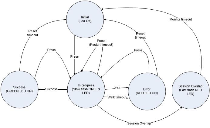
Timeout values are listed below -
- Reset timeout – 300 seconds
- Restart timeout – 120 seconds
- Walk timeout – 120 seconds
- Monitor timeout – 120 seconds
4.9 5G-WWC – General 5G WWC
The 5G-WWC set of requirements define a WAN behavior that is exclusive of the other behaviors defined in TR-124. For WWC this is referred to as 5G-RG mode of operation, and the non 5G behaviors are referred to as the FN-RG mode of operation. A device may be configured to exclusively use one mode of operation or the other, or may be a hybrid of the two via either VLAN or Ethertype separation of WAN traffic into distinct interfaces presenting a mix of 5G and non 5G interfaces to the device.
The following table illustrates the set of common and mode specific functionalities between the two modes of operation.
| Mutually exclusive requirements | |
|---|---|
| 5G-RG mode of operation | FN-RG mode of operation |
| 5G-WWC | WAN.CONNECT |
| 5G-WWC.FWA | WAN.CONNECT.ON-DEMAND |
| 5G-WWC.WAN | WAN.ETHOAM |
| 5G-WWC.Identifiers | WAN.DHCPC.force |
| 5G-WWC.WAN.CP | WAN.DHCPC.BFDecho |
| 5G-WWC.WAN.UP | WAN.IPv6 |
| 5G-WWC.WAN.UP.QOS | WAN.TRANS.6rd |
| WAN.TRANS.DSLite | |
| WAN.TRANS.v4-release-control | |
| WAN.TRANS.MAP-E | |
| WAN.PPP | |
| WAN.PPP.IPv6 | |
| WAN.dot1x | |
| Common Requirements | |
| WAN.DHCPC requirements | |
| WAN.IPv6 requirements 4, 5, 6, 7, 8, 9, 14, & 19 | |
| WAN.QOS requirements 3, 4, 9, 10, 11, & 12 | |
| WAN.QOS.VLAN | |
| MGMT.REMOTE.TR-069 |
Note - WAN.ATM & WAN.ATM.MULTI are out of scope.
It is recommended that implementers read TR-470 [7] 5G FMC Architecture Overview in conjunction with interpreting these requirements; in particular, the section 5G-RG Overview of Operation.
| ID | Requirement |
|---|---|
| 5G-WWC.1 | An RG that implements both modes of operation SHOULD be able to support both modes of operation simultaneously. |
| 5G-WWC.2 | An RG that implements both modes of operation MUST be able to be configured to disable the 5G-RG mode of operation |
| 5G-WWC.3 | An RG that implements both modes of operation MUST be able to be configured to disable the FN-RG mode of operation |
| 5G-WWC.4 | The RG SHOULD support URSP as specified in 3GPP TS 23.503 [18] with modification specified in 3GPP TS 23.316 [19]. |
| 5G-WWC.5 | The RG MUST support the 3GPP network slicing as defined in 3GPP TS.23.501 [20] clause 5.15 where the UE is replaced by the 5G-RG. |
| 5G-WWC.6 | The RG MUST support the 3GPP NSSAI configuration and NSSAI storage aspects as defined in TS 3GPP TS.23.501 [20] clause 5.15.4 where the UE is replaced by the 5G-RG. |
| 5G-WWC.7 | The RG MUST support to retrieve Configuration and Management from Controller or from ACS via PDU Session as specified in clause 9.6 of 3GPP TS 23.316 [19]. |
4.9.1 5G-WWC.Identifiers – 5G WWC Identifiers
| ID | Requirement |
|---|---|
| 5G-WWC.Identifiers.1 | The RG MUST be identified by 5G Subscription Permanent Identifier (SUPI) |
| 5G-WWC.Identifiers.2 | The SUPI for the RG MUST contain an IMSI. |
| 5G-WWC.Identifiers.3 | The SUPI format with IMSI for the RG MUST be as defined in 3GPP TS 23.003 [9] clause 2.2A |
| 5G-WWC.Identifiers.4 | When the RG needs to indicate its SUPI, for example during Registration procedure, the 5G-RG MUST provide the Subscription Concealed Identifier (SUCI)as defined in TS 33.501 |
| 5G-WWC.Identifiers.5 | The SUCI format provided by the RG MUST be as defined in 3GPP TS 23.003 [9] clause 2.2B |
| 5G-WWC.Identifiers.6 | The RG MUST support Permanent Equipment Identifier (PEI) |
| 5G-WWC.Identifiers.7 | For an RG that only has a wireline WAN interface, the PEI MUST include the MAC address of WAN interface and the format is defined in 3GPP TS 23.003 [9] |
| 5G-WWC.Identifiers.8 | For an RG that has a wireless WAN interface (and may also have a wireline WAN interface), the PEI MUST include an IMEI. The format is defined in 3GPP TS 23.003 [9]. |
| 5G-WWC.Identifiers.9 | The PEI MUST be stored in secure and tamper proof location in the RG as required by 3GPP TS 33.501 [22]. |
4.9.2 5G-WWC.FWA – 5G WWC Fixed Wireless Access
4.9.2.1 5G-WWC.FWA.IPTV – 5G WWC Fixed Wireless Access IPTV
| ID | Requirement |
|---|---|
5G-WWC.FWA.IPTV.1 |
The RG MUST support retrieve IPTV service via 5G network as specified in 3GPP TS 23.316 3GPP TS 23.316 [19] clause 7.7.1.1. Examples including the interactions between STB and 5G-RG are given in APPENDIX VII. The RG MUST distinguish the traffic belongs to Internet or IPTV network via the pre-configured traffic filters for IPTV and/or Internet in the RG and send the traffic to corresponding network. |
4.9.3 5G-WWC.WAN – 5G WWC Wide Area Network
| ID | Requirement |
|---|---|
| 5G-WWC.WAN.1 | The VLAN ID used for NAS, AS and 5WE encapsulated sessions MUST be able to be locally configured. Note: This is known as the 5G VLAN. |
| 5G-WWC.WAN.2 | The default VLAN ID used for NAS, AS and 5WE encapsulated PDU sessions is zero indicating an untagged or priority tagged UNI. |
| 5G-WWC.WAN.3 | The RG MUST support the procedures documented in Broadband Forum TR-456 [36] section ‘Procedure Call Flows’ subsection ‘For a 5G-RG’ and 3GPP TS 24.501 [17]. |
Note: A number of NAS procedures have error conditions that mandate the 5G-RG NAS implementation ‘back off’ for a period of time prior to re-attempting the operation. The set of procedures that result in these conditions is documented in 3GPP TS 24.501 [17]. The relevance of these various error, resource or subscription issue conditions to a 5G-RG in relation to the set of timers associated with NAS operations is discussed in Appendix 9.1 of Broadband Forum TR-456 [36].
4.9.3.1 5G-WWC.WAN.RADIO – 5G WWC Fixed Wireless Access Radio
| ID | Requirement |
|---|---|
5G-WWC.WAN.RADIO.1 |
The RG MUST support NAS protocol to interact with AMF as described in 3GPP TS 23.502 [21] specified in 3GPP TS 24.501 [17] in both cases with UE replaced with RG. In particular the following procedures (all clause references are 3GPP TS 23.502 [21]).
|
| 5G-WWC.WAN.RADIO.2 | The RG MUST support 5G-AN Protocol layer, including both control plane and user plane, to interact with NG-RAN which specified in 3GPP TS 38.300 [15]. |
5G-WWC.WAN.RADIO.3 |
The RG MUST support the following EPC procedures on the E-UTRA interface as described in 3GPP TS 23.401 [12] and specified in [13], in both cases with UE replaced by RG (note all clause references are to 3GPP TS 23.401 [12]):
|
| 5G-WWC.WAN.RADIO.4 | The RG MUST support E-UTRA Protocol layer, including both control plane and user plane, to interact with E-UTRAN which specified in 3GPP TS 36.300 [14]. |
| 5G-WWC.WAN.RADIO.5 | PLMN selections procedure defined in 3GPP TS 22.011 [8] and [11] MUST besupported. |
4.9.3.2 5G-WWC.WAN.CP – 5G WWC WAN Control Plane
| ID | Requirement |
|---|---|
| 5G-WWC.WAN.CP.1 | The RG MUST support the transport of NAS and AS information with the AGF as documented in “NAS and AS transport and information elements” section of Broadband Forum TR-456 [36]. |
| 5G-WWC.WAN.CP.2 | The RG SHOULD incorporate a random timing delay prior to attempting to initiate establishing 5G control connectivity. This random timing delay helps to reduce connection failures when a group of users attempts to establish connections to a service provider at the same time (e.g. after power is restored to a neighborhood that had a blackout). |
| 5G-WWC.WAN.CP.3 | The RG MUST use the RG’s WAN I/F Ethernet MAC address for the PPPoE 5G control plane connection. |
| 5G-WWC.WAN.CP.4 | The RG that is configured to support both modes of operation MUST be able to initiate a PPPoE 5G control plane connection using a NULL length service-name tag. |
| 5G-WWC.WAN.CP.5 | The RG that is configured to only support the 5G-RG mode of operation MUST use a PADI with a service-name of 5G (encoded as defined in Broadband Forum TR-456 [36] Section 5.2) when initiating a control plane connection. |
| 5G-WWC.WAN.CP.6 | An RG that does not receive a PADO in response to a PADI solicitation SHOULD re-try immediately to establish the connection. After three unsuccessful attempts, the RG SHOULD wait for five minutes, then repeat the connection attempt three times. If the PADI still fails, the RG SHOULD back off to thirty minute intervals between groups. |
| 5G-WWC.WAN.CP.7 | The RG attempting to initiate a PPPoE 5G control plane connection MUST include the LCP 5G VSO in the LCP Configure-Request. |
| 5G-WWC.WAN.CP.8 | The RG that receives a Configure-REJ to an LCP configure request containing the LCP 5G VSO MUST be able to revert to the FN-RG mode of operation and if it is configured to use PPPoE in that mode, continue the negotiation accordingly. |
| 5G-WWC.WAN.CP.9 | The RG that receives a Configure-REJ to an LCP configure request containing the LCP 5G VSO that intends to revert to IPoE operation MUST issue a PADT to terminate the PPPoE session. |
| 5G-WWC.WAN.CP.10 | The RG configured to only use the 5G-RG mode of operation, upon receipt of a Configure-REJ to a configure request containing the LCP 5G VSO MUST resort to an exponential backoff process to reinitiate a PPPoE 5G control plane connection. |
| 5G-WWC.WAN.CP.11 | An RG that is only configured to only use 5G procedures, and is unable to establish a 5G control plane connection (LCP Configure-REJ received) will issue a PADT to fully terminate the current attempt and then retry immediately. If that attempt fails it will delay 5 minutes prior to terminating the attempt and retrying. If that attempt fails, after each failure it will terminate the current attempt and select a random interval between 5 and 20 minutes until the next retry. |
| 5G-WWC.WAN.CP.12 | Removed. |
5G-WWC.WAN.CP.13 |
The RG MUST support NAS protocol to interact with AMF as specified in 3GPP TS 24.501 [17] with modification specified in 3GPP TS 23.316 [19] Note: The applicability of parameters in NAS messages and the applicability of specific NAS message is further defined in this document as well as 3GPP TS 23.316 [19], and 3GPP TS 24.501 [17]. |
| 5G-WWC.WAN.CP.14 | The RG MUST maintain a registration management state and a connection management state. The possible values for the registration management state are RM-DEREGISTERED and RM-REGISTERED. The possible values for the connection management state are CM-IDLE and CM-CONNECTED. The initial RG state is RM-DEREGISTERED and CM-IDLE. |
| 5G-WWC.WAN.CP.15 | The 5G-RG must start a NAS initial Registration procedure, as documented in 3GPP TS 23.316 [19] Section 7.2.1.1 and Broadband Forum TR-456 [36] Section “Registration Management Procedure for 5G-RG”. Upon completion of these procedures the RG will be in the RM-REGISTERED, CM-CONNECTED state. |
| 5G-WWC.WAN.CP.16 | The RG MUST use LCP-ECHO with a default periodicity of 10 seconds to monitor NAS channel liveliness. |
| 5G-WWC.WAN.CP.17 | Upon detection of connectivity failure an RG in the RM-REGISTERED/CM-CONNECTED state MUST transition the connection management state to CM-IDLE and initiate a deregistration timer to either the default value or the value communicated in the in NAS Registration Accept message as documented in 3GPP TS 24.501 [17] clause 8.2.7.17 |
| 5G-WWC.WAN.CP.18 | Upon expiry of the deregistration timer the RG MUST transition the registration management state to RM-DEREGISTERED and clean up all 5G context state. |
| 5G-WWC.WAN.CP.19 | An RG that has detected connectivity failure with the network MUST attempt to reconnect using the procedures outlined in requirement 5G-WWC.WAN.CP.16. |
| 5G-WWC.WAN.CP.20 | An RG that reconnects with the network while in the RM-REGISTERED state MUST use a NAS Service Request procedure, as documented int 3GPP TS 23.316 [19] Section 7.2.2.1 and Broadband Forum TR-456 [36] Section “5G-RG Service Request Procedure via W-5GAN”, to reestablish service. |
| 5G-WWC.WAN.CP.21 | An RG that reconnects with the network in the RM-DEREGISTERED state will re-establish service using the procedures outlined in requirements 1 through 15 above AND will cancel the deregistration timer. |
| 5G-WWC.WAN.CP.22 | An RG that receives a LCP Terminate-Request for the 5G Control plane connection will remove all PDU session state, all user plane state and terminate the control plane connection. |
| 5G-WWC.WAN.CP.23 | The RG MUST support RFC 4638 [107] procedures for negotiating PPP MTUs larger than 1492 bytes. |
| 5G-WWC.WAN.CP.24 | The RG MUST indicate the maximum PPP MTU it can support in the RFC 4638 [107] PPP-Max-Payload tag. |
| 5G-WWC.WAN.CP.25 | The RG MUST initiate LCP negotiations with the value it provided in the PPP-Max-Payload tag if echoed by the AGF, else falls back to 1492 as per RFC 2516 [67]. |
| 5G-WWC.WAN.CP.26 | The RG MUST use the MIN of negotiated PPP MTU and IPv4 Link MTU Parameter received via PCO at PDU Session Establishment time as the MTU for 5WE encapsulated IPv4 packets |
| 5G-WWC.WAN.CP.27 | The RG MUST use the MIN of negotiated PPP MTU and MTU option in the IPv6 RA received at PDU Session Establishment time for 5WE encapsulated IPv6 packets |
| 5G-WWC.WAN.CP.28 | An RG that supports both mode of operation MUST be able to conf-NAK an LCP request with authentication and continue the LCP procedure as specified TR-456 Issue 2 [36] section 5.3 |
Note: PLMN selection defined in 3GPP TS 22.011 [8] and in [10] are not applicable as described in clause 4.2.1 3GPP TS 23.316 [19].
4.9.3.3 5G-WWC.WAN.UP – 5G WWC WAN User Plane
| ID | Requirement |
|---|---|
| 5G-WWC.WAN.UP.1 | The RG MUST support the 5G WWC User Plane Encapsulation (5WE) as specified in RFC 8822 [148]. |
| 5G-WWC.WAN.UP.2 | The RG MUST support the IPv4, IPv6, IPv4/v6 and Ethernet PDU session types. |
5G-WWC.WAN.UP.3 |
The RG MUST use the same MAC address used for the PPPoE control plane connection for all PDU sessions. Note: Some ANs populate MAC anti-spoofing tables from the initial PADI received from an RG. Therefore for 5G operation the PPPoE control plane connection and the 5WE encapsulated PDU sessions are required to use a common MAC address. |
| 5G-WWC.WAN.UP.4 | The RG MUST use the same AGF MAC address for all PDU Sessions. |
| 5G-WWC.WAN.UP.5 | The RG MUST silently discard packets received with an unrecognized 5WE session ID value. |
| 5G-WWC.WAN.UP.6 | The RG MUST set the IPv4 MTU for the WAN interface to the minimum of the value negotiated using RFC 4638 [107] procedures and the IPv4 Link MTU parameter that the RG receives in the PDU SESSION ESTABLISHMENT ACCEPT message. |
| 5G-WWC.WAN.UP.7 | The RG MUST set the IPv6 MTU for the WAN interface to the minimum of the value negotiated using RFC 4638 [107] procedures and the MTU parameter that the RG receives in IPv6 RA messages received from the SMF. |
5G-WWC.WAN.UP.8 |
The RG MUST set the Ethernet MTU for the WAN interface to the minimum of the value of the Ethernet Max Frame Payload MTU value received via PCO and the RFC 4638 [107] negotiated MTU after adjustment for Ethernet header size. Note: A resulting WAN MTU of less than 1500 bytes is an error. Reporting and recover procedures are FFS. |
| 5G-WWC.WAN.UP.9 | The RG MUST support a minimum WAN MTU of 2k octets, and SHOULD support a minimum WAN MTU of 9k octets. |
4.9.3.3.1 5G-WWC.WAN.UP.QOS – 5G WWC WAN User Plane QoS
| ID | Requirement |
|---|---|
| 5G-WWC.WAN.UP.QOS.1 | The RG MUST support an “upstream QOS classifier table” maintained at the granularity of PDU session, that stores QOS rules and is used to perform filter matching on upstream traffic in order to associate specific flows with QFI. |
5G-WWC.WAN.UP.QOS.2 |
The RG MUST support population of the “upstream QOS classifier table” by NAS. |
| 5G-WWC.WAN.UP.QOS.3 | The RG MUST support population of the “upstream QOS classifier table” (including initializing an age out timer to the RQ timeout value for the session) with UE derived QOS rules with the filter information gleaned from the IP header and 5WE encoded QFI for packets received that have the RQI bit set in the 5WE header |
| 5G-WWC.WAN.UP.QOS.4 | When the RG receives a packet with RQI set where there already is a UE derived QOS rule for the gleaned filter information in the “upstream QOS classifier table” it MUST update the age out timer value to the RQ timeout value for the session and the QFI value to that gleaned from the current packet’s 5WE header. |
| 5G-WWC.WAN.UP.QOS.5 | When the RG forwards a packet upstream where it does not find a QOS rule filter match in the “upstream QOS classifier table”, it MUST mark the packet according to the default QFI for the PDU session. |
| 5G-WWC.WAN.UP.QOS.6 | When the RG forwards a packet upstream where it does find a filter match in the upstream QOS classifier table”, it MUST mark the packet according to the QFI associated with the QOS rule. |
| 5G-WWC.WAN.UP.QOS.7 | The RG MUST age out UE derived QOS rules populated as a result of downstream UP signaling (received RQI indication) upon expiry of the age out timer |
| 5G-WWC.WAN.UP.QOS.8 | The RG MUST remove all entries in the “upstream QOS classification table” associated with a PDU session at the time of session release. |
5G-WWC.WAN.UP.QOS.9 |
The RG MUST use the QFI to DSCP/PCP mappings for the PDU session received in the AS session parameters information. If the information is not present, the RG will revert to local configuration. Note: That mapping is unique per session, and the same QFI value used in two separate sessions may have a different mapping per session. |
5G-WWC.WAN.UP.QOS.10 |
When marking upstream packets according to the QFI to PCP/DSCP information received in the AS session parameters TLV, the RG MUST mark the Ethernet PCP according to the PCP information in the AS subscription parameters marking control sub-TLV:
Include the PCP information in a priority tag if the use of priority tagging is indicated via the P-bit being set in the marking controls or in local configuration, no marking for an untagged UNI if not indicated |
| 5G-WWC.WAN.UP.QOS.11 | When remarking upstream packets according to the QFI to PCP/DSCP information received in the AS session parameters TLV, the RG MUST remark the IP DSCP if upstream remarking is indicated in the subscription parameters marking control sub-TLV. |
4.9.3.4 5G-WWC.WAN.HO – 5G WWC Multi-access handover support
A device that is equipped with both a wireline and a radio interface (E-UTRA or NR) may implement resiliency on the basis of mobility hand-off. This can be in the wireline to wireless direction or vice versa.
| ID | Requirement |
|---|---|
| 5G-WWC.WAN.HO.1 | The RG MUST support mobility between the NG-RAN and W-5GAN based upon handover procedures triggered by the 5G-RG, and defined in clause 7.6 of 3GPP TS 23.316 [19] as well as in 3GPP TS 23.502 [21] clause 4.9.2.2, for 3GPP to Non-3GPP transition for a single-access PDU session (where “UE” is replaced by “5G-RG” and “N3IWF” by “W-5GAN”). |
| 5G-WWC.WAN.HO.2 | The RG MUST support mobility between E-UTRAN and W-5GAN based on handover procedures triggered by the 5G-RG as described in clause 7.6.4 of 3GPP TS 23.316 [19] and clause 4.11.3 of 3GPP TS 23.502 [21] (where “UE” is replaced by “5G-RG” and “N3IWF” by “W-5GAN”). |
4.9.3.5 5G-WWC.WAN.ATSSS – 5G WWC ATSSS
Access traffic steering switching and splitting (ATSSS) is used to permit a 5G-RG to simultaneously utilize both a 3GPP radio interface and non-3GPP wireline interface. The 3GPP radio interface may be with either a E-UTRAN (4G) or NG-RAN (5G). Requirements are specified for 5G operation, and 4G operation via EPC interworking.
Note that for the BBF WWC work, roaming on either interface is considered to be out of scope. What is in scope is referred to as Non-roaming and Roaming with Local Breakout architecture for ATSSS support in 3GPP TS.23.501 [20].
3GPP TS 23.502 [21] defines the procedures and 3GPP TS 24.193 [16] provides the stage 3 definition. Impacts to the NAS protocol for ATSSS is described in TS 24.501.
A rough narrative of operation is that:
5G-RG registers with a common PLMN on both the 3GPP and non-3GPP interfaces. In case the non-3GPP connectivity is available, the 5G-RG attempts to register via the non-3GPP interface first, because the Multi-Access PDU session from the 5G-RG can be initiated via the 3GPP interface, which requests the WAgfInfo availability in AMF and SMF to enable the co-located UPF selection. A security context is established with the first registration that is simply referenced by the second association via the 5G-GUTI.
The 5G-RG establishes a multi-access (MA) PDU session. Note that both the 3GPP radio and wireline interfaces may be 5G, or the 3GPP radio interface may be via LTE and employing EPS interworking. When both interfaces are 5G, this can be done with a single MA-PDU session establish request, assuming that the 5G-RG is already registered in both accesses before initiating the PDU Session Establishment procedure. When the radio interface is a E-UTRA interface, the ‘legs’ of the MA-PDU session must be separately established. During session establishment the 5G-RG is provided with ATSSS Rules that contain traffic distribution policies.
The 5G RG distributes traffic across the set of upstream interfaces according to ATSSS Rules received from the 5G System.
| ID | Requirement |
|---|---|
| 5G-WWC.WAN.ATSSS.1 | The RG MUST support ATSSS as is described in 3GPP TS.23.501 [20] |
| 5G-WWC.WAN.ATSSS.2 | The RG MUST support at least one of ATSSS-LL and MP-TCP proxy operation |
5G-WWC.WAN.ATSSS.3 |
The RG MUST support the following MA-PDU session lifecycle maintenance procedures described in 3GPP TS 23.502 [21] and specified in 3GPP TS 24.501 [17] and TS 24.193 with UE replaced by RG. The clauses referenced below refer to TS 23.502.
|
| 5G-WWC.WAN.ATSSS.4 | The RG MUST support EPC Interworking procedures for ATSSS as described in clause 4.22.6 of 3GPP TS 23.502 [21] and specified in 3GPP TS 24.193 [16], in both cases with UE replaced by RG. |
| 5G-WWC.WAN.ATSSS.5 | The RG MUST attempt to register via the wireline access first. (note: this will ensure the SMF can have the wAgfInfo available for the co-located UPF selection.) |
4.9.4 5G-WWC.LAN – 5G WWC LAN
4.9.4.1 5G-WWC.LAN.DHCPS – 5G WWC LAN DHCPv4
| ID | Requirement |
|---|---|
| 5G-WWC.LAN.DHCPS.1 | The embedded DHCPv4 server MUST include DHCP Option 26 (IP interface MTU) with an MTU value that is the MIN of the negotiated PPP MTU and the IPv4 Link MTU Parameter received from the SMF via PCO. |
4.9.4.2 5G-WWC.LAN.ADDRESSv6 – 5G WWC LAN SLAAC
| ID | Requirement |
|---|---|
5G-WWC.LAN.ADDRESSv6.1 |
The RG MUST set the MTU option of a Router Advertisement RFC 4691 [108] ADDRESSv6 to the MIN of negotiated PPP MTU and MTU option in the IPv6 RA MTU received from the SMF at PDU session initiation Note this supersedes requirement LAN.ADDRESSv6.8 |
Annex A: IPv6 Flow Diagrams
The flows in this annex are referenced by requirements in the body, and are therefore normative.
WAN PPPoE Automated Connection Flow
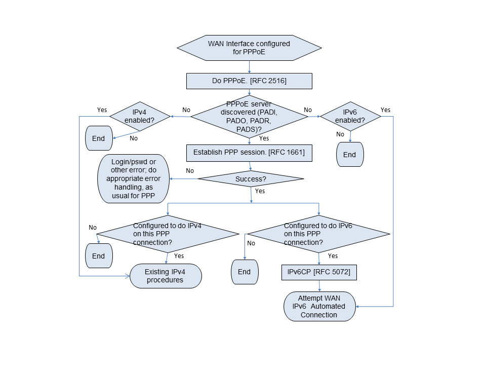
A.1 WAN IPv6 Automated Connection Flow
This flow assumes no manually configured prefix or address.
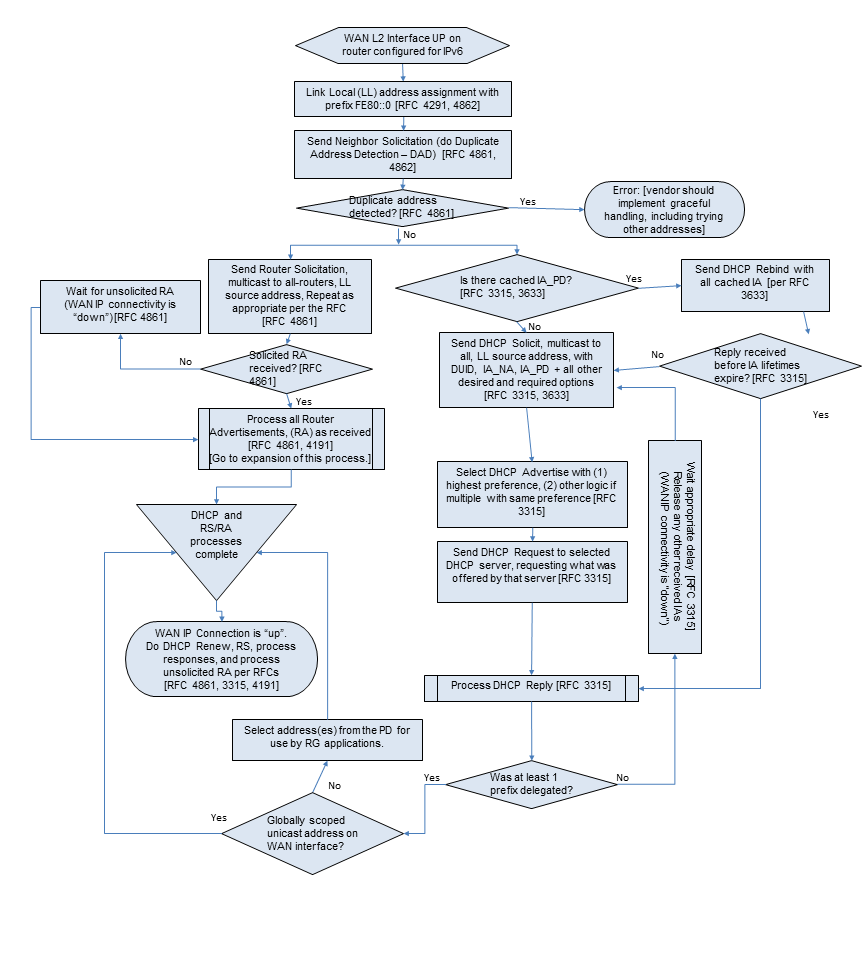
A.2 Receive Router Advertisement Subroutine Flow
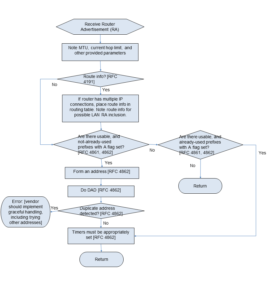
Appendix I: Application Level Gateway (ALG) and Port Forwarding List
This appendix is a partial list of applications and protocols that should work through the usage of predefined port forwarding configurations and ALGs. It is not a comprehensive list of all applications. It is expected that support for more applications will be needed with time.
D
DNS Server
F
FTP Client, FTP Server, FW1VPN
H
H.323, HTTP Server, HTTPS Server
I
ICMP Echo, IIMAP Client, IMAP Client v.3, IMAP server, Internet Phone, Internet Phone Addressing Server, IPsec Encryption, IPsec ESP, IPsec IKE, IRC
L
L2TP
M
mIRC DCC, IRC DCC, mIRC Chat, mIRC IDENT
N
NNTP Server, NTP
P
POP Client, POP3 Server, PPTP
R
RDP, Remote Desktop 32Rlogin/Rcp, RTSP
S
SDP, SIP, SMTP Server, SQL*NET Tools, SSH Secure Shell, SSH Server
T
Telnet Server
U
USENET News Service
W
Web Server, Windows 2000 Terminal Server
X
X Windows, XP Remote Desktop
Appendix II: Example Queuing for an RG
This section presents the queuing and scheduling discipline envisioned for upstream traffic through the RG in support of future service offerings delivered over the architecture described in TR-059.
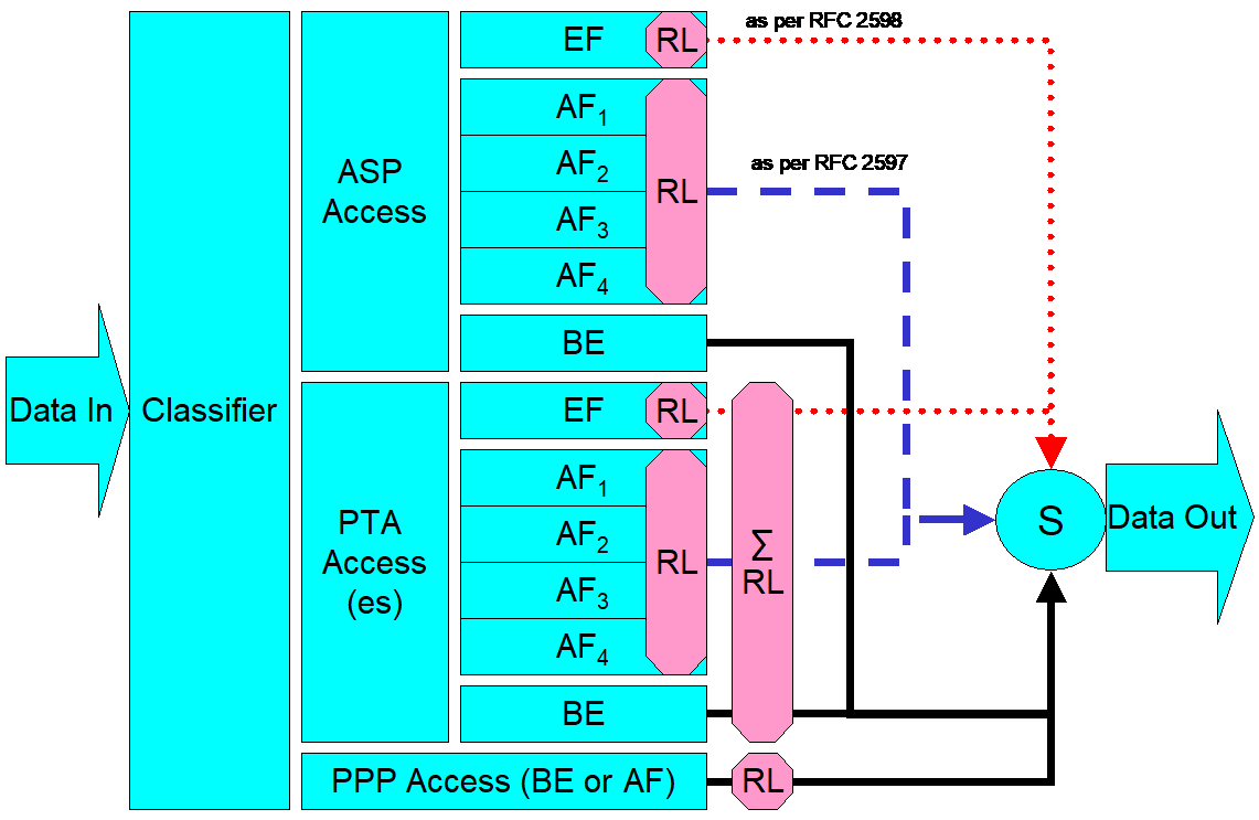
In Figure 5, the following abbreviations apply:
ASP – Application service provider
PTA – PPP terminated aggregation
PPP – Point-to-point protocol
EF – Expedited forwarding – as defined in IETF RFC 3246
AF – Assured forwarding – as defined in IETF RFC 2597
BE – Best effort forwarding
RL – Rate limiter
∑RL – Summing rate limiter (limits multiple flows)
S – Scheduler
Multiple access sessions are supported in this model. However, all traffic is classified and scheduled in a monolithic system. So, while it might appear at first that the Diffserv queuing and scheduling might apply only to IP-aware access, in fact all access, IP, Ethernet, or PPP is managed by the same system that adheres to the Diffserv model.
For example, at the bottom of Figure 5, BE (best effort) treatment is given to the non-IP-aware access sessions (PPPoE started behind the RG or delivered to an L2TP tunnel delivery model). This queue might be repeated several times in order to support fairness among multiple PPPoE accesses, or it might be a monolithic queue with separate rate limiters applied to the various access sessions.
The PTA access is a single block of queues. This is done because NSP access typically works with a single default route to the NSP, and managing more than one simultaneously at the RG would be perilous. The ∑ rate limiter would limit the overall access traffic for a service provider.
Rate limiters are also shown within the EF and AF service classes because the definition of those diffserv types is based on treating the traffic differently when it falls into various rates.
Finally, at the top of the diagram is the ASP access block of queues. In phase 1A of the TR-059 architecture, these queues are provisioned and provide aggregate treatment of traffic mapped to them. In phase 1B, it will become possible to assign AF queues to applications to give them specific treatment instead of aggregate treatment. The EF service class may also require a high degree of coordination among the applications that make use of it so that its maximum value is not exceeded.
Notable in this architecture is that all the outputs of the EF, AF, and BE queues are sent to a scheduler (S) that pulls traffic from them in a strict priority fashion. In this configuration EF traffic is, obviously, given highest precedence and BE is given the lowest. The AF service classes fall in between.
Note that there is significant interest in being able to provide a service arrangement that would allow general Internet access to have priority over other (bulk rate) services.1 Such an arrangement would be accomplished by assigning the bulk rate service class to BE and by assigning the default service class (Internet access) as AF with little or no committed information rate.
Given this arrangement, the precedence of traffic shown in the figure is arranged as:
EF – red dotted line
AF – blue dashed line (with various precedence among AF classes as described in IETF RFC 2597)
BE – black solid line
Appendix III: Routed Architecture – Examples of Potential Configurations
III.1 Introduction
The pictures and descriptions in the following scenarios are intended to provide examples of the interworking of many of the requirements in this document.
Since the single PC case is a simple subset of the multi-PC case (except when explicitly using the single PC mode of operation (LAN.DHCPS.19)), it will not be directly addressed. The network used in this sequence of examples has 5 PCs, which are described as being connected over Ethernet. For purposes of these scenarios, neither the physical network nor the nature of the attached devices is significant.
III.2 Basic RG as Router Initiating One or More PPPoE Sessions
The four scenarios that follow build on one another to describe a number of the capabilities required in this document. They show PPPoE being used in all cases for WAN connectivity, with the embedded DHCP server in the RG enabled.
III.2.1 No WAN Connection
The router has no WAN connection up.
The router has been configured to give PC2 its WAN address via its embedded DHCP server. Since the router has no WAN connection, it will give PC2 a private address with a 10 minute lease time (as defined in LAN.DHCPS.12).
PC5 has been configured with a static IP address.
PCs 1-4 are configured to make DHCP requests. The router responds to all DHCP requests with IP addresses in the range of 192.168.1.64 to 192.168.1.253 (LAN.DHCPS.8), an IP gateway address (and LAN-side address of the device) of 192.168.1.254 (LAN.DHCPS.14), a DNS server address of 192.168.1.254 (LAN.DNS.1) and an IP address lease time for all PCs but PC2 of 24 hours (LAN.DHCPS.11).
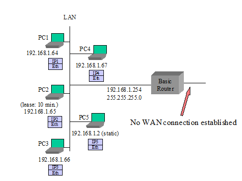
III.2.2 Router Sets Up PPPoE to an ISP
This scenario is the same as presented in the “No WAN Connection” example above with the following exceptions:
The router sets up a PPPoE session to ISP – it obtains an IP address and DNS server addresses via IPCP (WAN.PPP.1)
The router gives its public IP address to PC2 (LAN.DHCPS.18) when PC2’s lease expires.
The router is configured to allow PC2 to communicate with other devices on the LAN (LAN.ADDRESS.8).
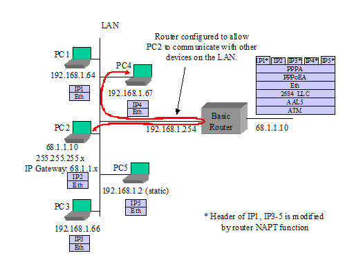
III.2.3 PC3 Sets Up Its Own PPPoE Session
This scenario is the same as presented in III.2.1 with the following exceptions:
- PC3 uses a PPPoE client to establish its own PPPoE session. While the private IP address from the router is still associated with PC3’s Ethernet interface, PC3 also has a public IP address associated with its own PPPoE interface. Common behavior is for all IP traffic of PC3 to now use this PPPoE interface (WAN.PPP.10, LAN.FWD.5).
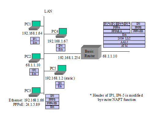
III.2.4 Router Sets Up a Second PPPoE Session
This scenario is the same as presented in III.2.1 with the following exceptions:
The router sets up second PPPoE session (PPPoEC). It gets an IP address and DNS addresses through IPCP. It gets routing information from RIP-2 (LAN.FWD.15), manual entry, or other mechanisms (LAN.FWD.8). PPPoEA remains the default route (LAN.FWD.20).
PC5 requests a DNS lookup for a URL. The router sends simultaneous URL lookup requests to DNS servers on both PPPoE connections. The DNS server on the PPPoEA connection fails to resolve the URL and the PPPoEC connection returns an IP address. The router returns the IP address to PC5 (LAN.DNS.3).
PC5 sends IP packets to the returned IP address. The router determines from its routing table that this goes to the PPPoEC connection.
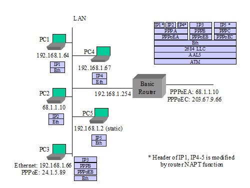
III.3 “RFC 2684 Bridged” Mode
The next three scenarios deal IETF RFC 2684 bridged mode configuration cases where the network is not expecting a PPP login or the router is not doing PPP. The first case has the router using its DHCP client to the WAN, acting as a DHCP server to the LAN, and doing routing and NAPT to PCs on the LAN. The second case has the router not establishing a WAN connection, and individual PCs setting up their own PPPoE sessions. In the third case, the router’s embedded DHCP server is also disabled, and the PCs are getting IP addresses from the WAN.
III.3.1 Router in IP-routed “RFC 2684 Bridged” Mode, Embedded DHCP Server On
The router provides an IP address to each device that it receives a DHCP request from.
PC5 uses a static IP address and does not send a DHCP request to the router.
The router has been configured to give PC2 its WAN address. When the router has no WAN connection, it gives PC2 a private address with a short lease time.
The router issues a DHCP request and establishes an IP session to the WAN (WAN.ATM.3, WAN.ATM.4, LAN.FWD.1).
The router gives its public IP address to PC2.
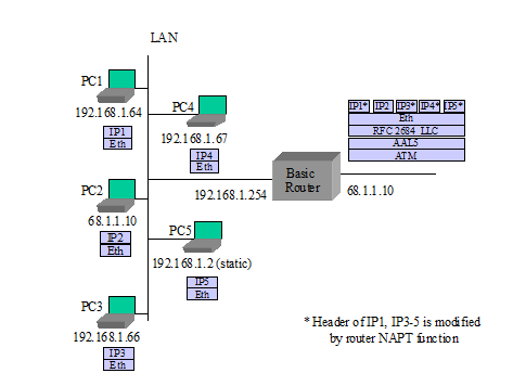
III.3.2 Router in Bridged Mode, Embedded DHCP Server On
The router provides a private IP address to each device that it receives a DHCP request from (LAN.DHCPS.3).
The router does not establish any IP or PPP sessions to the WAN.
No device can get a DHCP response from the WAN, since the router will intercept all DHCP requests that come to it.
PC1 and PC3 each use a PPPoE client to establish their own PPPoE sessions (WAN.PPP.10, LAN.FWD.5). While the private IP address from the router is still associated with their PC Ethernet interfaces, PC1 and PC3 also have a public IP address associated with their respective PPPoE interfaces. Common behavior is for all IP traffic of PC1 and PC3 to now use their own PPPoE interfaces.
PCs that do not establish their own PPPoE connection cannot connect to the WAN, but they can communicate with other PCs on the LAN.
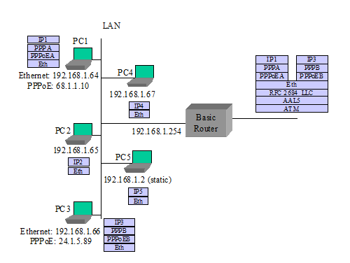
III.3.3 Router in Bridged Mode, Embedded DHCP Server Off
The router does not establish any IP or PPP sessions to the WAN.
All DHCP requests are bridged onto the WAN (WAN.BRIDGE.1).
In this example, PC5 does not have a static IP address.
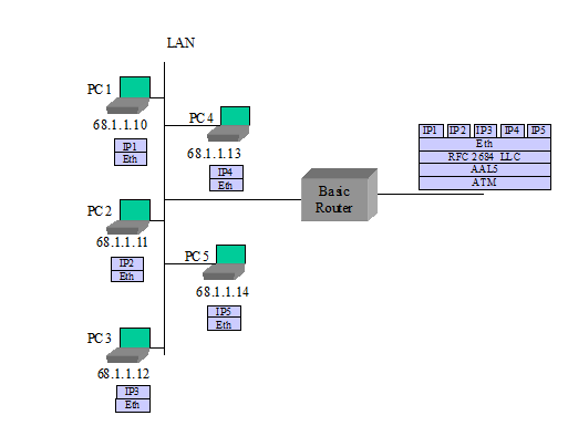
III.4 Single PC Mode of Operation
The router is configured to use the single PC mode of operation (LAN.DHCPS.19).
The router’s embedded DHCP server is on. The embedded DHCP server has only one address lease available in this case.
PC1 is the first device seen, so it is identified as the “single PC”.
PC1 is provided with a private IP address and 1:1 NAT is performed between the WAN and PC1 by the router. The subnet mask sent to PC1 is 255.255.255.0.
Alternately PC1 could be given the router’s public address instead, as with PC2 in the scenarios in section III.2.
III.5 Simultaneous IP and PPPoE WAN Sessions
TR-059 requirements have PPPoE and IP sessions running simultaneously over the same PVC. Here are some examples of how this might look, assuming the network is capable of terminating PPPoE and IP at the same time on the same PVC.
Note: Simultaneous IP and PPPoE is not well supported in the network today. Most equipment terminating the ATM PVC does not support both IP and PPPoE connections at the same time.
III.5.1 Router in IP-routed “2684 Bridged” Mode, Embedded DHCP Server On
The router provides an IP address to each device that it receives a DHCP request from.
PC5 uses a static IP address and does not send a DHCP request to the router.
The router has been configured to give PC2 its WAN address. When the router has no WAN connection, it gives PC2 a private address with a 10 minute lease time.
The router issues a DHCP request and establishes an IP session to the WAN.
The router gives its public IP address to PC2.
PC3 uses a PPPoE client to establish its own PPPoE session (WAN.PPP.10, LAN.FWD.5). While the private IP address from the router is still associated with PC3’s Ethernet interface, PC3 also has a public IP address associated with its own PPPoE interface. Common behavior is for all IP traffic of PC3 to now use this PPPoE interface.
III.5.2 Router Sets Up IP as a Second Session
Assuming the scenario in section III.2.3 as a base, add:
The router sets up connection IPC (LAN.FWD.19). It gets an IP address and DNS addresses through a DHCP client request. It gets routing information from RIP-2 (LAN.FWD.15). PPPoEA remains the default route.
PC5 requests a DNS lookup for a URL. The router sends simultaneous URL lookup requests to DNS servers on both connections. The DNS server on the PPPoEA connection fails to resolve the URL and the IPC connection returns an IP address. The router returns the IP address to PC5 (LAN.DNS.3).
PC5 sends IP packets to the returned IP address. The router determines from its routing table that this goes to connection IPC.
III.6 Router Embedded DHCP Server Gives Out Public IP Addresses (from use of IPCP extension)
The router initially gives private IP addresses to PCs, before setting up its PPPoE session.
The router sets up PPPoE to ISP and gets IP address and DNS server addresses via IPCP. It also gets a subnet mask via an IPCP extension (WAN.DHCPC.1, WAN.PPP.12).
The router gives public IP addresses to certain PCs when they issue DHCP requests again (LAN.DHCPS.18).
PC5 is set for static IP and does not issue a DHCP request.
Appendix IV: Bridged Architecture – Examples of Potential Configurations
IV.1 Introduction
The pictures and descriptions in the following scenarios are intended to provide examples of the bridge interworking of many of the requirements in this document.
The network used in this sequence of examples has 5 PCs, which are described as being connected over Ethernet. For purposes of these scenarios, the physical network and the exact nature of the connected devices are not relevant.
IV.2 Managed Bridge
The RG will have an IP address for management as (described in section WAN.BRIDGE), which is obtained using a DHCP client on the WAN interface. This address can also be used for other gateway originated services such as an attached telephony device.
The DHCP server of the RG is configured with the appropriate IP address range and subnet mask by the Controller.
The PCs are configured to use DHCP for assignment of an IP address. All DHCP requests from the PCs are processed by the DHCP server (described in section LAN.DHCPS] on the RG. Note that the scope of these addresses is specific to the service provider network (i.e. they may be public or private depending on the access network design). If private, it is assumed that the service provider has the NAT functionality in its network.
All subsequent data exchanges between the PCs and the RG are performed using 802.1D bridging techniques (described in section WAN.BRIDGE).
The RG filters specific message types (e.g. UPnP or DHCP) from being sent to the WAN (described in section LAN.FW).
IV.2.1 Local Management
- The RG may allow access to a local management interface via a default address (described in section LAN.ADDRESS).
IV.3 Unmanaged Bridge
The RG does not establish any layer 3 connectivity to the WAN.
All DHCP requests from the PCs are bridged to the WAN (described in section WAN.BRIDGE).
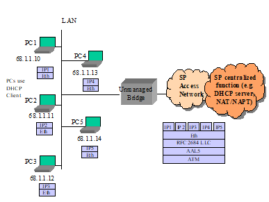
IV.3.1 Local Management
- The RG may allow access to a local management interface via a default address (described in section LAN.ADDRESS).
Appendix V: Sealing Current References
Sealing current is also known in the telecommunications industry as wetting current. Sealing current may be sourced by the ATU-C in certain service providers that deploy “dry loop” DSL circuits, meaning that DSL is delivered in the absence of typical central office or remote terminal fed analog POTS service on the copper pair.
The following functional diagram depicts a sealing current circuit design specified in the IF.WAN.SEALING optional module that can be implemented on an xDSL residential gateway.
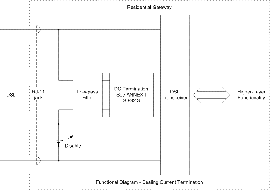
Appendix VI: Product Profile Template
VI.1 Introduction
To accommodate the many different residential gateway implementations that will be needed due to various localized market needs, LAN/WAN interfaces, and different services that will be delivered in operators’ networks, TR-124 endeavors to define a superset of general requirements and optional modules that can be implemented on a residential gateway.
In order to create a specific product based on the TR-124 modularized requirements, it is necessary for either the Broadband Forum (in the form of new TR documents) or for individual network operators to specify the following details to define a specific desired product implementation:
A filled out product profile matrix template as shown in the example below to indicate required modules
Any line item edits to requirements (changes to current TR-124 requirements).
Any additional new requirements that are needed in the product.
Any configuration defaults needed. These should refer to TR-124 requirements that establish a different or new default value required in the implementation.
Localized regulatory, certifications, powering and product labeling requirements as necessary.
VI.2 Instructions for Completing a Product Profile Template
The following instructions apply to filling out the product profile template below:
Any modules marked with a check mark will be considered required, meaning that all MUST requirements in that section are to be satisfied (with the exception of any specific line item edits that have been made as discussed in section VI.1).
Any modules that are not marked with a check MAY be implemented on the product, but are not considered required. Any vendor implementing any module, regardless of being considered required or not, MUST comply with all MUST requirements in the module (i.e. partial implementations of a module MUST NOT be provided).
If a module is explicitly not to be included in the product, it must be marked with an x mark to indicate that it MUST NOT be included.
For the optional LAN/WAN modules, where appropriate it may be necessary to specify the number or ports/lines to be implemented (e.g. “Qty. 4” under the IF.LAN.ETH.SWITCH to indicate 4 ports).
VI.3 Product Profile Template
| Section | Title | Required? (check,x , or blank) |
|---|---|---|
| GEN | General Device Requirements | |
| DESIGN | Design | |
| OPS | Device Operation | |
| NET | Networking Protocols | |
| NETv6 | IPv6 Networking Protocols | |
| WAN | Wide Area Networking (WAN) | |
| ATM | ATM | |
| ATM.MULTI | ATM Multi-PVC | |
| CONNECT | Connection Establishment | |
| CONNECT.ON-DEMAND | On-Demand Connection Establishment | |
| ETHOAM | Ethernet OAM | |
| BRIDGE | Bridging | |
| DHCPC | DHCP Client (DHCPv4) | |
| DHCPC.FORCE | Force renew | |
| DHCPC.BFDecho | BFD echo | |
| DHCPC.BFDKA | BFD Keep-alive | |
| DHCPv4 | DHCP Client (DHCPv4) | |
| DHCPv4.ERP | EAP Reauthentication (ERP) for DHCPv4 | |
| DHCPv6 | DHCP Client (DHCPv6) | |
| DHCPv6.ERP | EAP Reauthentication (ERP) for DHCPv6 | |
| IPv6 | IPv6 WAN Connection | |
| TRANS.6rd | 6rd Transition Mechanism | |
| TRANS.DS-LITE | Dual Stack Lite Transition Mechanism | |
| TRANS.V4-release-control | IPv6 connectivity with content-based IPv4 release control transition mechanism | |
| TRANS.MAP-E | IPv6 connectivity with content-based IPv4 release control transition mechanism | |
| PPP | PPP Client | |
| PPP.IPv6 | PPP Client for establishment of IPv6 connection | |
| dot1x | 802.1x Client | |
| DoS | Denial of Service Prevention | |
| QoS | Quality of Service | |
| QoS.VLAN | VLAN based QoS | |
| QoS.TUNNEL | Quality of Service for Tunneled Traffic | |
| IPsecClient | IPsec VPN peer to peer | |
| L2tpClient | L2tp VPN Remote Access | |
| PCP | Port Control Protocol | |
| WAN.TUN | WAN Tunnel | |
| LAN | Local Area Networking (LAN) | |
| GEN | General LAN Protocols | |
| ADDRESS | Private IPv4 Addressing | |
| ADDRESSv6 | LAN IPv6 Addressing | |
| DHCPS | DHCPv4 Server | |
| DHCPv6S | DHCPv6 Server | |
| DNS | Naming Services (IPv4 and general requirements) | |
| DNSv6 | Naming Services (IPv6) | |
| NAT | NAT/NAPT | |
| PFWD | Port Forwarding (IPv4) | |
| PFWDv6 | Port Forwarding (IPv6) | |
| ALG | ALG Functions (IPv4) | |
| FWD | Connection Forwarding | |
| IGMP.BRIDGED | IGMP and Multicast in Bridged Configurations (IPv4) | |
| IGMP.ROUTED | IGMP and Multicast in Routed Configurations (IPv4) | |
| MLD.ROUTED | MLD and Multicast in Routed Configurations (IPv6) | |
| FW | Firewall (Basic) | |
| FW.SPI | Firewall (Advanced) | |
| FILTER.TIME | Time of Day Filtering | |
| FILTER.CONTENT | Content Filtering | |
| DIAGNOSTICS | Automated User Diagnostics | |
| CAPTIVE | Captive Portal with Web Redirection | |
| QOS | LAN quality of service requirements | |
| SIPserver | SIP Server | |
| SIPmixer | SIP Mixer | |
| Interworking.UE-Authentication | 3GPP User Equipment Authentication Support | |
| MGMT | Management & Diagnostics | |
| GEN | General | |
| UPnP | UPnP | |
| UPnP.IGD | UPnP IGD | |
| UPnP.IGD.ACRF | UPnP IGD to allow Connection Request Forwarding | |
| LOCAL | Local Management | |
| LOCAL.TR-064 | TR-064 Issue 2 | |
| REMOTE.TR-069 | Remote Management (TR-069) | |
| REMOTE.USP | Remote Management (USP) | |
| REMOTE.WEB | Remote Management (Web Browser) | |
| NTP | Network Time Client | |
| MGMT.DATCOL | Data collection Requirements | |
| MGMT.DATCOL.WIFIDIAG | Wi-Fi Diagnostics Data Collection | |
| IF.WAN | WAN Interface Modules | Enter Quantity |
| ADSL | ADSL and ADSL2+ | |
| VDSL2 | VDSL2 | |
| xDSL | xDSL General Requirements | |
| xDSL.INP | xDSL INP Values | |
| xDSL.BOND | xDSL Bonding | |
| xDSL.REPORT | xDSL Reporting of Physical Layer Issues | |
| xDSL.SEALING | DC Sealing Current | |
| xDSL.SURGE | AC Power Surge Protection | |
| ETH | Ethernet (WAN) | |
| GPON | GPON | |
| XG-PON | 10G PON | |
| XGS-PON | XGS PON | |
| MoCA | MoCA (WAN) | |
| IF.LAN | LAN Interface Modules | Enter Quantity |
| ETH | Ethernet (LAN) | |
| ETH.SWITCH | Ethernet Switch | |
| USB.PC | USB (PC) | |
| VOICE.ATA | Voice ATA Ports | |
| WIRELESS.AP | Wireless: General Access Point Functions | |
| WIRELESS.AP.WEP | Wireless: Wired Equivalent Privacy | |
| WIRELESS.AP.WPA2 | Wireless: WPA2-Personal | |
| WIRELESS.AP.WPA3 | Wireless: WPA3-Personal | |
| WIRELESS.AP.WPA2-Enterprise | Wireless: WPA2-Enterprise | |
| WIRELESS.AP.WPA3-Enterprise | Wireless: WPA3-Enterprise | |
| WIRELESS.AP.ERP-Authenticator | Wireless: ERP Authenticator | |
| WIRELESS.11g | Wireless: 802.11g Access Point | |
| WIRELESS.11a | Wireless: 802.11a Access Point | |
| WIRELESS.11h | Wireless: 802.11h Access Point | |
| WIRELESS.11n | Wireless: 802.11n Access Point | |
| WIRELESS.11ac | Wireless: 802.11ac Access Point | |
| WIRELESS.11ax | Wireless: 802.11ax Access Point | |
| HomePNA | HomePNA (Phoneline/Coax) | |
| MoCA | MoCA (LAN) | |
| HomePlugAV | HomePlug AV (LAN) | |
| HomePlugAV2 | HomePlug AV2 (LAN) | |
| Ghn | G.hn | |
| SEC | Security | |
| GEN | General security | |
| USERINTERFACE | User Interface security | |
| RGSMART | Smart Residential Gateway | |
| OPLAT | Open platform Support | |
| OPLAT.OSGI | Open platform Support : OSGI Open platform | |
| OPLAT.EE | Open platform Support : Execution Environment | |
| REGIONAL | Regional Annexes | |
| NA.Power | North American Power and Environmental | |
| NA.LED | North American LED Indicators |
End of Broadband Forum Technical Report TR-124
This “bulk rate” service class would typically be used for background downloads and potentially for peer-to-peer applications as an alternative to blocking them entirely.↩︎