
4.8 REGIONAL – Regional
Annexes 
4.8.1 REGIONAL.NA – North American
4.8.1.1 REGIONAL.NA.POWER – North
American Power and Environmental
| ID | Requirement | |||||||||||||||
|---|---|---|---|---|---|---|---|---|---|---|---|---|---|---|---|---|
| REGIONAL.NA.POWER.1 |
The RG MUST be UL 60950 listed. | |||||||||||||||
| REGIONAL.NA.POWER.2 |
The RG MUST display proof of CSA (Canadian Standards Association) or ULC (Underwriters Laboratories Canada) certification for CAN/CSA C22.2 No. 60950. This is the Canadian equivalent to, and is identical to, UL 60950. | |||||||||||||||
REGIONAL.NA.POWER.3 |
The RG MUST meet all requirements when operating with the following line voltages: Brownout: 96 to 127 Vac @ 60 +/- 0.1 Hz Reserve: 105 to 129 Vac @ 60 +/- 3.0 Hz |
|||||||||||||||
| REGIONAL.NA.POWER.4 |
If the power supply is external to the RG, it MUST be UL 1310 or UL 60950 listed and certified. | |||||||||||||||
| REGIONAL.NA.POWER.5 |
The RG MUST comply with FCC Part 15 rules for Class B devices. | |||||||||||||||
| REGIONAL.NA.POWER.6 |
The RG MUST comply with Industry Canada ICES-003 Class B requirements. | |||||||||||||||
| REGIONAL.NA.POWER.7 |
The RG MUST comply with the requirements of Telcordia® GR-1089-CORE, Electromagnetic Compatibility and Electrical Safety – Generic Criteria for Network Telecommunications Equipment. Class A3 source voltages are not permitted. | |||||||||||||||
REGIONAL.NA.POWER.8 |
The RG MUST support the following environmental conditions:
|
4.8.1.2 REGIONAL.NA.LED – North
American LED Indicators
| ID | Requirement |
|---|---|
REGIONAL.NA.LED.1 |
The RG MUST have at a minimum the following indicator lights (labeling of all ports is subject to localized requirements): Power Ethernet Broadband Internet |
| REGIONAL.NA.LED.2 |
All physical ports and bridged connection types on the RG (e.g. Ethernet, USB, Wireless, HomePlug, G.hn, HomePNA, 1394, etc…) MUST have a link integrity indicator lamp on the RG (1 per port if a separate physical port is present or per connection type if a separate port is not present). |
| REGIONAL.NA.LED.3 |
The indicator lights MUST be in the order as indicated in requirement REGIONAL.NA.LED.1 in a left to right or top to bottom orientation. |
| REGIONAL.NA.LED.4 |
Port indicator lights for all additional LAN Interfaces (beyond the standard Ethernet indicator) MUST be placed between the “Ethernet” and “Broadband” lights defined in requirement REGIONAL.NA.LED.1 (note that labeling of all ports is subject to localized requirements). |
| REGIONAL.NA.LED.5 |
All port indicator lights MUST be located on the front of the RG unless summary indicator lights are used. |
REGIONAL.NA.LED.6 |
Physical port indicator lights MAY be located next to the port and other than on the front of the RG, so long as there is a summary indicator light for the associated interface type with the other port indicator lights on the front of the unit. For example, there may be Ethernet port indicator lights located on the back of the RG by each Ethernet connection as long as there is a summary indicator for the Ethernet connections on the front of the RG in the standard location. |
| REGIONAL.NA.LED.7 |
The indicator lights MUST be readily visible (99% human observer detection in less than 250 milliseconds) at 4 meters with an ambient illumination level of 5920 meter-candles. Visibility MUST be maintained over a horizontal viewing angle of +/- 80 degrees and a vertical viewing angle of -20 to +45 degrees off the central axis. |
| REGIONAL.NA.LED.8 |
When flashing, the indicator lights MUST flash at 4 Hz with a duty cycle of 50% (except as specified otherwise in this document). |
REGIONAL.NA.LED.9 |
The RG MUST have an On/Off power indicator light. The power indicator MUST function as follows: Solid Green = Power on Off = Power off Red = POST (power on self test) failure (not bootable) or RG malfunction. A malfunction is any error of internal sequence or state that will prevent the RG from connecting to the access network or passing customer data. This may be identified at various times such after power on or during operation through the use of self testing or in operations that result in a unit state that is not expected or should not occur. |
REGIONAL.NA.LED.10 |
The RG MUST have an indicator light that indicates broadband interface layer connectivity. This indicator MUST function as follows: Solid green = Broadband physical connection is established (e.g. DSL sync) Off = Broadband interface powered off, no signal detected Flashing green = Signal detected, in process of synchronizing Flashing at 2 Hz with a 50% duty cycle when trying to detect carrier signal Flashing at 4 Hz with a 50% duty cycle when the carrier has been detected and trying to train |
| REGIONAL.NA.LED.11 |
If additional broadband interfaces (2 or more) are supported that operate simultaneously with the primary broadband link (e.g. xDSL bonding, Ethernet simultaneous with xDSL, etc.), the RG MUST support a broadband light to indicate the status of each link. The behavior for this indicator MUST follow the requirements described in REGIONAL.NA.LED.10. |
REGIONAL.NA.LED.12 |
The RG MUST have an Internet indicator light that indicates whether or not it has at least one broadband WAN interface active. This indicator MUST function as follows: Solid green = IP connected (the RG has a WAN IP address from IPCP/DHCP/static and broadband link is up) and no traffic detected. If the IP or PPPoE session is dropped due to an idle timeout, the light will remain green if an ADSL connection is still present. If the session is dropped for any other reason, the light is turned off. The light will turn red when it attempts to reconnect and DHCP or PPPoE fails. Off = Broadband physical connection power off, RG in bridged mode with no IP address assigned to the RG, or broadband physical interface connection not present Flickering green = IP connected and IP traffic is passing thru the RG (either direction) Red = RG attempted to become IP connected and failed (no 802.1X, DHCP, PPPoE, PPPoA response or authentication failure, etc.) |
REGIONAL.NA.LED.13 |
A LAN interface physical port indicator light MUST function as follows: Solid green = Powered device connected to the associated port (includes devices with wake-on-LAN capability where a slight voltage is supplied to an Ethernet connection) Flickering green = LAN activity present (traffic in either direction) Off = No activity, RG power off, no cable or no powered device connected to the associated port. |
| REGIONAL.NA.LED.14 |
If the RG supports the Wi-Fi protected setup (WPS) pushbutton configuration (PBC) method (IF.LAN.WIRELESS.AP.11), the RG SHOULD have a two-color LED to display the status of WPS PBC. The operation of this LED SHOULD be as described in 4.8.1.3 “WPS LED operation” below. |
| REGIONAL.NA.LED.15 |
The indicator for Wi-Fi protected setup pushbutton method, if present, MUST be located within close proximity to the pushbutton or next to the Wireless status indicator. |
4.8.1.3 WPS LED
operation - WLAN WPS PBC Security
- Green - On for 5min or until pressed again
The Wi-Fi protected setup (WPS, previously called “simple config”) has been completed successfully.
- Green Slow flash (2 Hz 50% duty cycle)
The Wi-Fi protected setup PBC procedure is in progress.
- Red - Solid
Error unrelated to security, such as failed to find any partner, or protocol prematurely aborted. Recommended user action - press WPS button to start protocol again.
- Red - Fast flash (4 Hz 50% duty cycle)
Session overlap detected (possible security risk). Recommended user action - Wait for 2 minutes, then press WPS button again to reattempt. If the condition recurs, refer the user to PIN-based configuration method.
- Off
The device is ready for another PBC authentication
Note - This is a deviation from the three color indicator option and behaviors described by the Wi-Fi Alliance, which however, will not enforce any LED behavior as part of its WPS certification process.
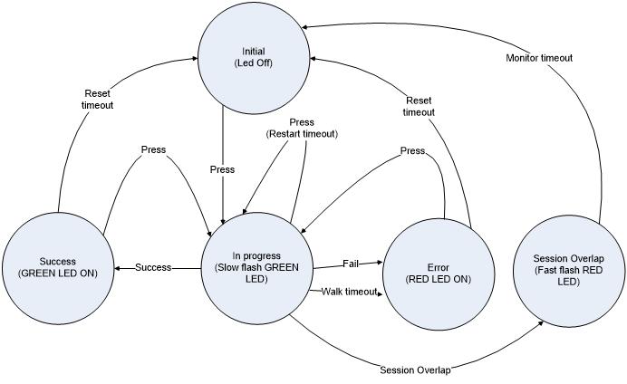
Timeout values are listed below -
- Reset timeout – 300 seconds
- Restart timeout – 120 seconds
- Walk timeout – 120 seconds
- Monitor timeout – 120 seconds