
Appendix
III: Routed Architecture – Examples of Potential
Configurations 
III.1 Introduction
The pictures and descriptions in the following scenarios are intended to provide examples of the interworking of many of the requirements in this document.
Since the single PC case is a simple subset of the multi-PC case (except when explicitly using the single PC mode of operation (LAN.DHCPS.19)), it will not be directly addressed. The network used in this sequence of examples has 5 PCs, which are described as being connected over Ethernet. For purposes of these scenarios, neither the physical network nor the nature of the attached devices is significant.
III.2
Basic RG as Router Initiating One or More PPPoE Sessions
The four scenarios that follow build on one another to describe a number of the capabilities required in this document. They show PPPoE being used in all cases for WAN connectivity, with the embedded DHCP server in the RG enabled.
III.2.1 No WAN
Connection
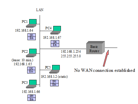
The router has no WAN connection up.
The router has been configured to give PC2 its WAN address via its embedded DHCP server. Since the router has no WAN connection, it will give PC2 a private address with a 10 minute lease time (as defined in LAN.DHCPS.12).
PC5 has been configured with a static IP address.
PCs 1-4 are configured to make DHCP requests. The router responds to all DHCP requests with IP addresses in the range of 192.168.1.64 to 192.168.1.253 (LAN.DHCPS.8), an IP gateway address (and LAN-side address of the device) of 192.168.1.254 (LAN.DHCPS.14), a DNS server address of 192.168.1.254 (LAN.DNS.1) and an IP address lease time for all PCs but PC2 of 24 hours (LAN.DHCPS.11).
III.2.2
Router Sets Up PPPoE to an ISP
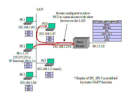
This scenario is the same as presented in the “No WAN Connection” example above with the following exceptions:
The router sets up a PPPoE session to ISP – it obtains an IP address and DNS server addresses via IPCP (WAN.PPP.1)
The router gives its public IP address to PC2 (LAN.DHCPS.18) when PC2’s lease expires.
The router is configured to allow PC2 to communicate with other devices on the LAN (LAN.ADDRESS.8).
III.2.3
PC3 Sets Up Its Own PPPoE Session
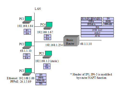
This scenario is the same as presented in III.2.1 with the following exceptions:
- PC3 uses a PPPoE client to establish its own PPPoE session. While the private IP address from the router is still associated with PC3’s Ethernet interface, PC3 also has a public IP address associated with its own PPPoE interface. Common behavior is for all IP traffic of PC3 to now use this PPPoE interface (WAN.PPP.10, LAN.FWD.5).
III.2.4 Router Sets Up a
Second PPPoE Session
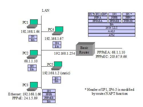
This scenario is the same as presented in III.2.1 with the following exceptions:
The router sets up second PPPoE session (PPPoEC). It gets an IP address and DNS addresses through IPCP. It gets routing information from RIP-2 (LAN.FWD.15), manual entry, or other mechanisms (LAN.FWD.8). PPPoEA remains the default route (LAN.FWD.20).
PC5 requests a DNS lookup for a URL. The router sends simultaneous URL lookup requests to DNS servers on both PPPoE connections. The DNS server on the PPPoEA connection fails to resolve the URL and the PPPoEC connection returns an IP address. The router returns the IP address to PC5 (LAN.DNS.3).
PC5 sends IP packets to the returned IP address. The router determines from its routing table that this goes to the PPPoEC connection.
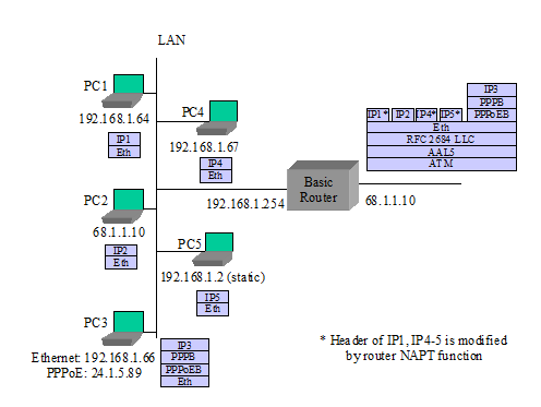
III.3 “RFC 2684
Bridged” Mode
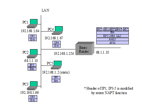
The next three scenarios deal IETF RFC 2684 bridged mode configuration cases where the network is not expecting a PPP login or the router is not doing PPP. The first case has the router using its DHCP client to the WAN, acting as a DHCP server to the LAN, and doing routing and NAPT to PCs on the LAN. The second case has the router not establishing a WAN connection, and individual PCs setting up their own PPPoE sessions. In the third case, the router’s embedded DHCP server is also disabled, and the PCs are getting IP addresses from the WAN.
III.3.1
Router in IP-routed “RFC 2684 Bridged” Mode, Embedded DHCP Server On
The router provides an IP address to each device that it receives a DHCP request from.
PC5 uses a static IP address and does not send a DHCP request to the router.
The router has been configured to give PC2 its WAN address. When the router has no WAN connection, it gives PC2 a private address with a short lease time.
The router issues a DHCP request and establishes an IP session to the WAN (WAN.ATM.3, WAN.ATM.4, LAN.FWD.1).
The router gives its public IP address to PC2.
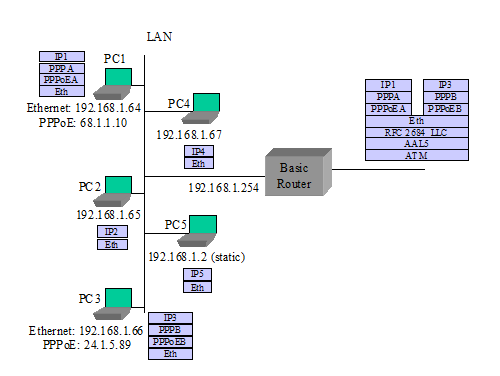
III.3.2 Router
in Bridged Mode, Embedded DHCP Server On
The router provides a private IP address to each device that it receives a DHCP request from (LAN.DHCPS.3).
The router does not establish any IP or PPP sessions to the WAN.
No device can get a DHCP response from the WAN, since the router will intercept all DHCP requests that come to it.
PC1 and PC3 each use a PPPoE client to establish their own PPPoE sessions (WAN.PPP.10, LAN.FWD.5). While the private IP address from the router is still associated with their PC Ethernet interfaces, PC1 and PC3 also have a public IP address associated with their respective PPPoE interfaces. Common behavior is for all IP traffic of PC1 and PC3 to now use their own PPPoE interfaces.
PCs that do not establish their own PPPoE connection cannot connect to the WAN, but they can communicate with other PCs on the LAN.
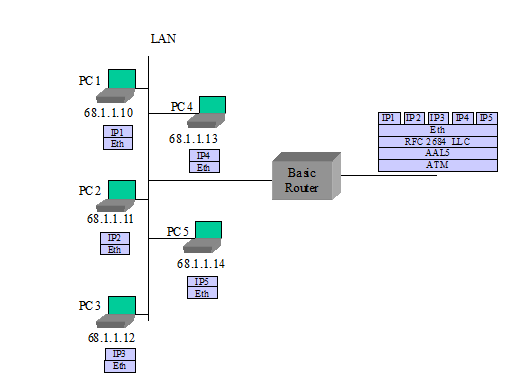
III.3.3 Router
in Bridged Mode, Embedded DHCP Server Off
The router does not establish any IP or PPP sessions to the WAN.
All DHCP requests are bridged onto the WAN (WAN.BRIDGE.1).
In this example, PC5 does not have a static IP address.
III.4 Single
PC Mode of Operation
The router is configured to use the single PC mode of operation (LAN.DHCPS.19).
The router’s embedded DHCP server is on. The embedded DHCP server has only one address lease available in this case.
PC1 is the first device seen, so it is identified as the “single PC”.
PC1 is provided with a private IP address and 1:1 NAT is performed between the WAN and PC1 by the router. The subnet mask sent to PC1 is 255.255.255.0.
Alternately PC1 could be given the router’s public address instead, as with PC2 in the scenarios in section III.2.
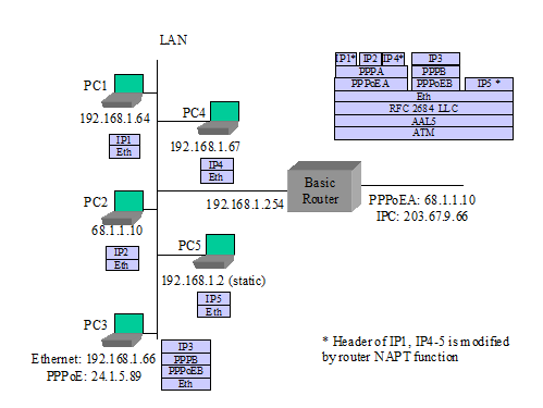
III.5 Simultaneous IP
and PPPoE WAN Sessions
TR-059 requirements have PPPoE and IP sessions running simultaneously over the same PVC. Here are some examples of how this might look, assuming the network is capable of terminating PPPoE and IP at the same time on the same PVC.
Note: Simultaneous IP and PPPoE is not well supported in the network today. Most equipment terminating the ATM PVC does not support both IP and PPPoE connections at the same time.
III.5.1
Router in IP-routed “2684 Bridged” Mode, Embedded DHCP Server On
The router provides an IP address to each device that it receives a DHCP request from.
PC5 uses a static IP address and does not send a DHCP request to the router.
The router has been configured to give PC2 its WAN address. When the router has no WAN connection, it gives PC2 a private address with a 10 minute lease time.
The router issues a DHCP request and establishes an IP session to the WAN.
The router gives its public IP address to PC2.
PC3 uses a PPPoE client to establish its own PPPoE session (WAN.PPP.10, LAN.FWD.5). While the private IP address from the router is still associated with PC3’s Ethernet interface, PC3 also has a public IP address associated with its own PPPoE interface. Common behavior is for all IP traffic of PC3 to now use this PPPoE interface.
III.5.2 Router Sets Up IP
as a Second Session
Assuming the scenario in section III.2.3 as a base, add:
The router sets up connection IPC (LAN.FWD.19). It gets an IP address and DNS addresses through a DHCP client request. It gets routing information from RIP-2 (LAN.FWD.15). PPPoEA remains the default route.
PC5 requests a DNS lookup for a URL. The router sends simultaneous URL lookup requests to DNS servers on both connections. The DNS server on the PPPoEA connection fails to resolve the URL and the IPC connection returns an IP address. The router returns the IP address to PC5 (LAN.DNS.3).
PC5 sends IP packets to the returned IP address. The router determines from its routing table that this goes to connection IPC.
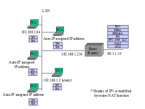
III.6
Router Embedded DHCP Server Gives Out Public IP Addresses (from use of
IPCP extension)
The router initially gives private IP addresses to PCs, before setting up its PPPoE session.
The router sets up PPPoE to ISP and gets IP address and DNS server addresses via IPCP. It also gets a subnet mask via an IPCP extension (WAN.DHCPC.1, WAN.PPP.12).
The router gives public IP addresses to certain PCs when they issue DHCP requests again (LAN.DHCPS.18).
PC5 is set for static IP and does not issue a DHCP request.