
Appendix II:
Example Queuing for an
RG 
This section presents the queuing and scheduling discipline envisioned for upstream traffic through the RG in support of future service offerings delivered over the architecture described in TR-059.
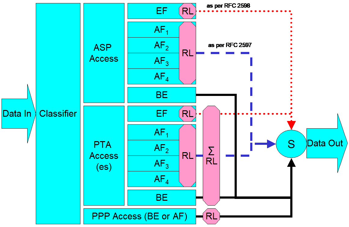
In Figure 5, the following abbreviations apply:
ASP – Application service provider
PTA – PPP terminated aggregation
PPP – Point-to-point protocol
EF – Expedited forwarding – as defined in IETF RFC 3246
AF – Assured forwarding – as defined in IETF RFC 2597
BE – Best effort forwarding
RL – Rate limiter
∑RL – Summing rate limiter (limits multiple flows)
S – Scheduler
Multiple access sessions are supported in this model. However, all traffic is classified and scheduled in a monolithic system. So, while it might appear at first that the Diffserv queuing and scheduling might apply only to IP-aware access, in fact all access, IP, Ethernet, or PPP is managed by the same system that adheres to the Diffserv model.
For example, at the bottom of Figure 5, BE (best effort) treatment is given to the non-IP-aware access sessions (PPPoE started behind the RG or delivered to an L2TP tunnel delivery model). This queue might be repeated several times in order to support fairness among multiple PPPoE accesses, or it might be a monolithic queue with separate rate limiters applied to the various access sessions.
The PTA access is a single block of queues. This is done because NSP access typically works with a single default route to the NSP, and managing more than one simultaneously at the RG would be perilous. The ∑ rate limiter would limit the overall access traffic for a service provider.
Rate limiters are also shown within the EF and AF service classes because the definition of those diffserv types is based on treating the traffic differently when it falls into various rates.
Finally, at the top of the diagram is the ASP access block of queues. In phase 1A of the TR-059 architecture, these queues are provisioned and provide aggregate treatment of traffic mapped to them. In phase 1B, it will become possible to assign AF queues to applications to give them specific treatment instead of aggregate treatment. The EF service class may also require a high degree of coordination among the applications that make use of it so that its maximum value is not exceeded.
Notable in this architecture is that all the outputs of the EF, AF, and BE queues are sent to a scheduler (S) that pulls traffic from them in a strict priority fashion. In this configuration EF traffic is, obviously, given highest precedence and BE is given the lowest. The AF service classes fall in between.
Note that there is significant interest in being able to provide a service arrangement that would allow general Internet access to have priority over other (bulk rate) services.1 Such an arrangement would be accomplished by assigning the bulk rate service class to BE and by assigning the default service class (Internet access) as AF with little or no committed information rate.
Given this arrangement, the precedence of traffic shown in the figure is arranged as:
EF – red dotted line
AF – blue dashed line (with various precedence among AF classes as described in IETF RFC 2597)
BE – black solid line