
Appendix
IV: Bridged Architecture – Examples of Potential
Configurations 
IV.1 Introduction
The pictures and descriptions in the following scenarios are intended to provide examples of the bridge interworking of many of the requirements in this document.
The network used in this sequence of examples has 5 PCs, which are described as being connected over Ethernet. For purposes of these scenarios, the physical network and the exact nature of the connected devices are not relevant.
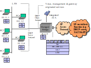
IV.2 Managed Bridge
The RG will have an IP address for management as (described in section WAN.BRIDGE), which is obtained using a DHCP client on the WAN interface. This address can also be used for other gateway originated services such as an attached telephony device.
The DHCP server of the RG is configured with the appropriate IP address range and subnet mask by the Controller.
The PCs are configured to use DHCP for assignment of an IP address. All DHCP requests from the PCs are processed by the DHCP server (described in section LAN.DHCPS] on the RG. Note that the scope of these addresses is specific to the service provider network (i.e. they may be public or private depending on the access network design). If private, it is assumed that the service provider has the NAT functionality in its network.
All subsequent data exchanges between the PCs and the RG are performed using 802.1D bridging techniques (described in section WAN.BRIDGE).
The RG filters specific message types (e.g. UPnP or DHCP) from being sent to the WAN (described in section LAN.FW).
IV.2.1 Local Management
- The RG may allow access to a local management interface via a default address (described in section LAN.ADDRESS).
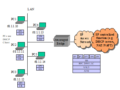
IV.3 Unmanaged Bridge
The RG does not establish any layer 3 connectivity to the WAN.
All DHCP requests from the PCs are bridged to the WAN (described in section WAN.BRIDGE).
IV.3.1 Local
Management
- The RG may allow access to a local management interface via a default address (described in section LAN.ADDRESS).